www.ti.com
1.8-V and 3.3-V Power Supply
11
SNAU244–July 2019
Submit Documentation Feedback
Copyright © 2019, Texas Instruments Incorporated
Modes of Operations
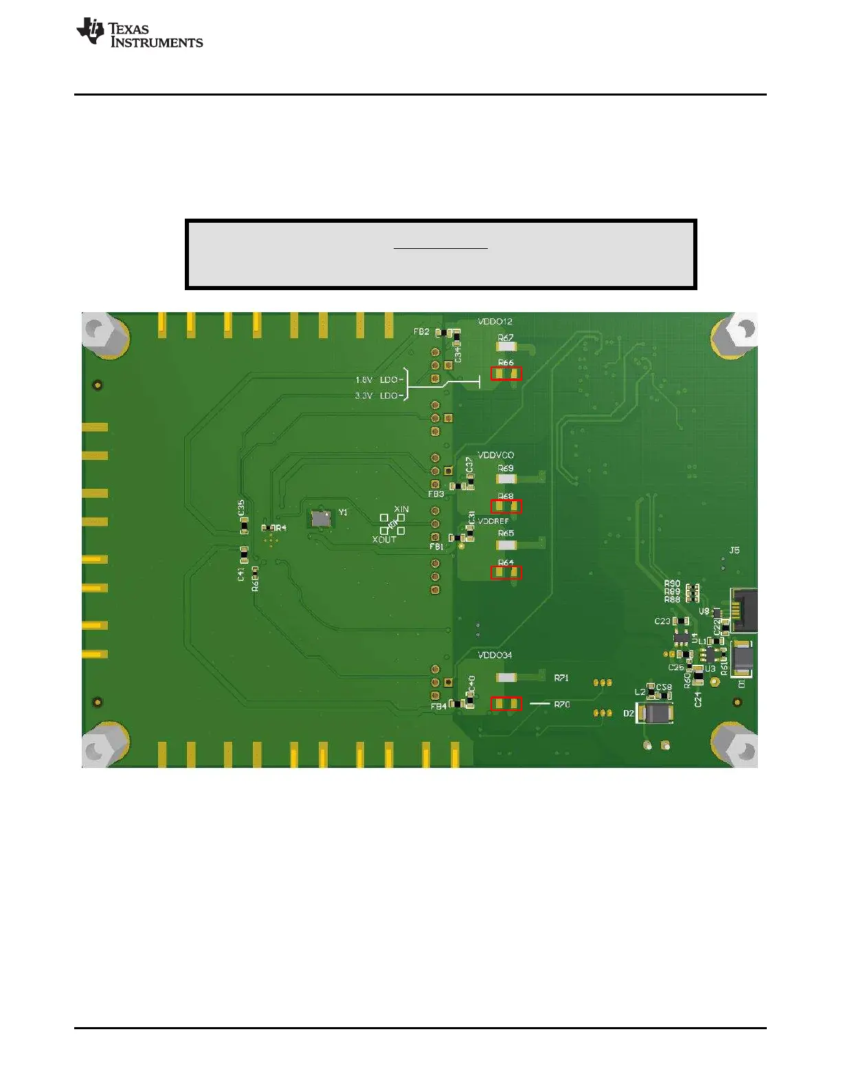
2.5 1.8-V and 3.3-V Power Supply
The 3.3-V LDOs are disabled by default, and the 1.8-V LDOs are controlled by J26. To enable the 1.8-V
LDOs, short pin 2 and 3 of J26. To disable the 1.8-V LDOs, remove the jumper for J26. To use 3.3-V
LDO, the designer must first populate the four 0-Ω resistors: R64, R66, R68, and R70. After the resistors
are populated, the 3.3-V LDOs are controlled by jumper J25. To enable the 3.3-V LDOs, short pin 2 and 3
of J25. To disable the 3.3-V LDOs, remove the jumper for J25.
WARNING
Do NOT enable 1.8-V and 3.3-V LDOs at the same time.
Figure 2-2. Board Rework Guide to Enable 3.3-V Supply
 Loading...


