Check Outputs
www.ti.com
8
SNAU244–July 2019
Submit Documentation Feedback
Copyright © 2019, Texas Instruments Incorporated
Quick Start
1.6 Check Outputs
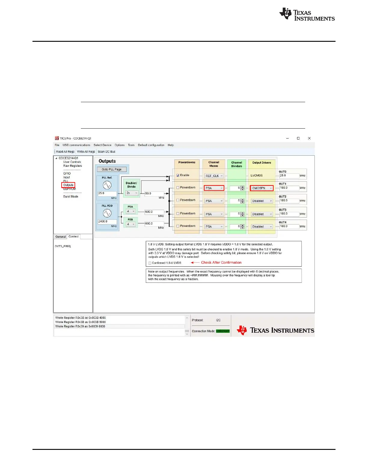
The output frequency is saved as 1 MHz by default. To change the output frequency, go to the "Output"
page and update the text in Channel Muxes or Output Drivers columns shown in Figure 1-5. Change the
format of output 1 to "CMOSPN" to select the CMOS format output for both OUT1_P and OUT1_N, then
connect the SMA_OUT1P (J15) or SMA_OUT1N (J17) to an oscilloscope. With 50-Ω DC termination, see
the 100 MHz and close to 900 mV—half of the supply voltage with cable/connector loss—swing on the
scope.
NOTE: Only the SDA/GPIO2 and SCL/GPIO3 pins are connected to the on-board microcontroller.
The other pins can only be configured by the on-board jumpers or connected to an external
controller. They cannot be controlled by TICS Pro.
Figure 1-5. Configure Outputs