www.ti.com
Configure Jumpers
5
SNAU244–July 2019
Submit Documentation Feedback
Copyright © 2019, Texas Instruments Incorporated
Quick Start
1.3 Configure Jumpers
To configure the jumpers:
1. Unplug the USB from the EVM to disconnect the power.
2. Short J23 to power the on-board LDOs with a 5-V source from the USB. Short pins 2 and 3 of J26 to
enable 1.8-V LDOs.
3. Short pin 2 of J6 and pin 1 of J9. Short pin 2 of J10 and pin 1 of J13. The purpose of this step is to
connect SCL and SDA pins of DUT to the on-board microcontroller in order to enable I2C
programming.
4. Short pin 1 and 2 of J12 to pull the REFSEL pin low. When the REFSEL pin is low, select the
secondary reference and use an on-board 25-MHz crystal as the reference source.
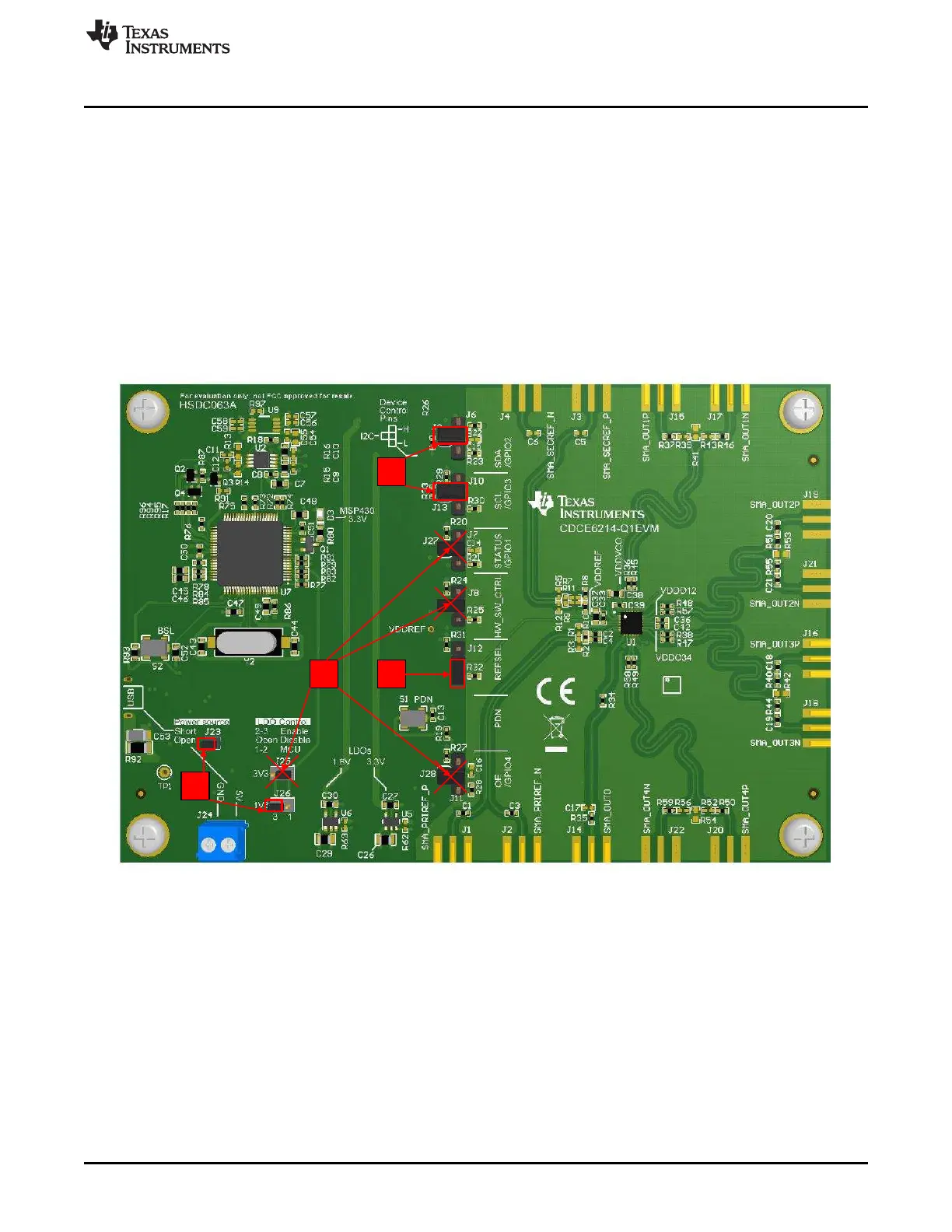
5. Remove all other jumpers or leave them floating by connecting them to only one pin. The position of
J25 is not important because the resistors required to enable a 3.3-V rail are not populated by default.
Figure 1-2. Jumper Configuration Guideline