www.ti.com
How to Use External Microcontroller
13
SNAU244–July 2019
Submit Documentation Feedback
Copyright © 2019, Texas Instruments Incorporated
Frequently Asked Questions - FAQ
3.2 How to Use External Microcontroller
The designer can use an external USB2ANY (http://www.ti.com/tool/USB2ANY) and blue wire the EVM.
However, the designer can only use a 3.3-V power supply because the USB2ANY only supports a 3.3-V
I2C bus.
3.2.1 Use 3.3-V Power Supply and Configure Jumpers
First follow the instructions on Section 2.5 to rework the board to enable 3.3-V LDOs. Follow these steps
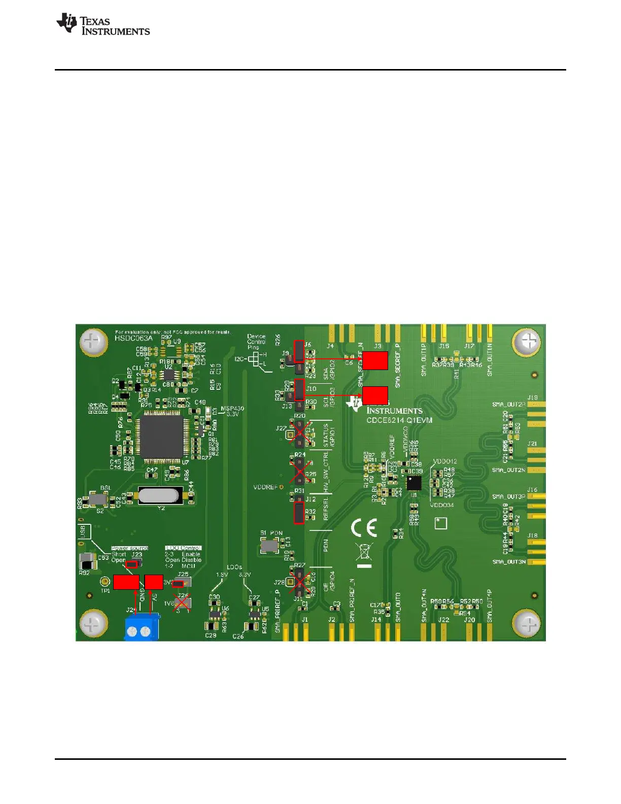
and refer to Figure 3-2 to configure the jumpers
• Short J23. Short pins 2 and 3 of J25 and remove jumper for J26 to enable 3.3-V LDOs and disable
1.8-V LDOs.
• Short pins 2 and 3 of J6 and pins 2 and 3 of J10. The purpose is to disconnect the SDA and SCL pins
of DUT from on-board micocontroller and pull the SDA/SCL to VDDREF (3.3 V) through a 4.7-kΩ
resistor.
• Short pins 1 and 2 of J12 to use SECREF and on-board crystal.
• Remove all other jumpers (J7, J8, and J11).
• Connect GND, 5 V to ground, and the 5-V supply separately. Connect SDA (pin 2 of J6), SCL (pin 2 of
J10), and GND to USB2ANY. Refer to Figure 3-2 for details on how to connect these three wires to
USB2ANY.
Figure 3-2. EVM Blue Wire Guide