www.ti.com
Functional Description
2.1.4 User Switches and RGB User LED
The Tiva C Series LaunchPad comes with an RGB LED. This LED is used in the preloaded RGB
quickstart application and can be configured for use in custom applications.
Two user buttons are included on the board. The user buttons are both used in the preloaded quickstart
application to adjust the light spectrum of the RGB LED as well as go into and out of hibernation. The user
buttons can be used for other purposes in the user’s custom application.
The evaluation board also has a green power LED. Table 2-2 shows how these features are connected to
the pins on the microcontroller.
Table 2-2. User Switches and RGB LED Signals
GPIO Pin Pin Function USB Device
PF4 GPIO SW1
PF0 GPIO SW2
PF1 GPIO RGB LED (Red)
PF2 GPIO RGB LED (Blue)
PF3 GPIO RGD LED (Green)
2.1.5 Headers and BoosterPacks
The two double rows of stackable headers are mapped to most of the GPIO pins of the TM4C123GH6PM
microcontroller. These rows are labeled as connectors J1, J2, J3, and J4. Connectors J3 and J4 are
located 0.1 in (2.54 mm) inside of the J1 and J2 connectors. All 40 header pins of the J1, J2, J3, and J4
connectors make up the Tiva C Series TM4C123G LaunchPad BoosterPack XL Interface. Table 2-3
through Table 2-6 show how these header pins are connected to the microcontroller pins and which GPIO
functions can be selected.
NOTE: To configure the device peripherals easily and intuitively using a graphical user interface
(GUI), see the Tiva C Series Pinmux Utility found at www.ti.com/tool/lm4f_pinmux. This easy-
to-use interface makes setting up alternate functions for GPIOs simple and error-free.
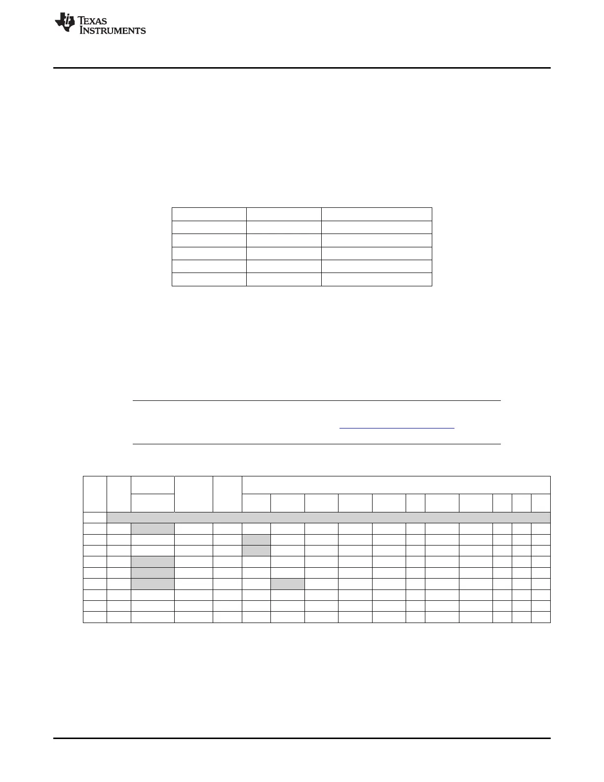
Table 2-3. J1 Connector
(1)
Analog
Tiva C
GPIOPCTL Register Setting
On-
Function
Series
J1 Pin GPIO board
MCU
GPIO
Function
1 2 3 4 5 6 7 8 9 14 15
Pin
AMSEL
1.01 3.3 V
1.02 PB5 AIN11 – 57 – SSI2Fss – M0PWM3 – – T1CCP1 CAN0Tx – – –
1.03 PB0 USB0ID – 45 U1Rx – – – – – T2CCP0 – – – –
1.04 PB1 USB0VBUS – 46 U1Tx – – – – – T2CCP1 – – – –
1.05 PE4 AIN9 – 59 U5Rx – I2C2SCL M0PWM4 M1PWM2 – – CAN0Rx – – –
1.06 PE5 AIN8 – 60 U5Tx – I2C2SDA M0PWM5 M1PWM3 – – CAN0Tx – – –
1.07 PB4 AIN10 – 58 – SSI2Clk – M0PWM2 – – T1CCP0 CAN0Rx – – –
1.08 PA5 – – 22 – SSI0Tx – – – – – – – – –
1.09 PA6 – – 23 – – I2C1SCL – M1PWM2 – – – – – –
1.10 PA7 – – 24 – – I2C1SDA – M1PWM3 – – – – – –
(1)
Shaded cells indicate configuration for compatibility with the MSP430 LaunchPad.
9
SPMU296–April 2013 Hardware Description
Submit Documentation Feedback
Copyright © 2013, Texas Instruments Incorporated

 Loading...


