~
TEXAS
INSTRUMENTS
INTRODUCTlON
The Texas
lnstruments
Disk
Memory
Drive is a
high-speed,
highvolu-
me
memory
device. The
disk
drive reads information !rom and writes
information o n a
5-1/4
inch
diskette
(noi
included).ll
can read
orwrile
inlormation l rom any piace o n
the
diskette,
and
can
rapidly locate any
position
or
file o n
lhe
diskette. The
disk
drive spins the
diskette
al a
constant
speed and
controls
the movement
ol
the magnetized head.
T o
lunction
properly, a
disk
drive
musi
h ave a
disk
controllar. The Disk
Drive Controller tells the
disk
drive
where
to
position
the
magnetic
h e ad in
order
lo
read
or
write
inlormation
properly. The
controller
al
so
puts
a catalog on the disk, making the data that has been written easy
t o locate. The
controller
does
these
things
in
response
t o
commands
which
you
choose
with the Disk Manager, n LOGO,
Editor/
Assembler,
and
other
Sol
id
State Cardridge Com m an d
Modules
or
in response
lo
the statements in a n BASIC program.
This manual
conlains
only
the set-up,
and
service, information
!or
the
Disk
Memory
Drive. For
instructions
regarding setup, test, and opera-
tion or the
complete
disk
system, please refer
lo
the
Disk
Memory
System manual
includcd
with the Disk Drive Controller.
Two
possible
configurations
exisl in
lhe
type of
disk
drives you can
set-up. First, you can h ave an
internai
disk
drive that is
specially
tailo-
red
to
fil
i~side
the Peripheral Expansion
System
and
up
lo
two
exter-
nal drives.
Second, you
can
have
up
lo
three external drives
connec-
ted lo the system.
DISK
DRIVE
INFORMA
nON
As it
comes
!rom the factory, a
disk
drive is ready to run as the
only
drive on
your
system. Il you are using
more
t han
onc
drive,
complete
the
following steps
!or
ali
but
o
ne
o!
the
drive
s.
The las t external drive
should
be
connected
withoul
being
altered.
DO THE
FOLLOWING
ONL
Y IF YOU
ARE USING TWO
OR
THREE DRIVES!
1.
WARNING:
All
POWER CORDS
MUST
BE DISCONNECTED
FROM
THE POWER
OUTLETS
DURING
THE
FOLLOWING
PRO-
CEDURE!
2.
T o remove the cover,
do
one
of the following.
e Internai Disk
Drive-
On
the side
otthe
disk
drive is a tab !oca-
led
near the
back
of the drive. O n the
back
of the drive is a hole
designed
lo
help Iii! l h e
lab
lo
remove
the
disk
drive cover. Re-
move the
cover
by
lifting
lhc
tab
and
lhen
sliding
out
the drive's
conlents.
e Exlernal
Disk
Drive-
O n ali
bui
o
ne
of
your
drive
s.
usc
a Phil-
lips-head
screwdriver
lo
remove the six screws
lhat
hold
lhe
cover. Lift
lhe
cover
oH.
3.
Locate the main printed
circuii
board. O n il, locate the terminalion
resister pack. lt
has
14
leads
an d
looks
like an inlegrated circuii.
(Note:
The main
boards
look
slighlly
different
on
the
internai and
external drives,
but
the
pack
is in
the
same piace o n each.) Be ca-
retul not
lo
disturb
the strapping
pack
(or
shunl
pack,
which
is
al
so
removabte) located very near the resislor pack.
lDIIIIlillillDI
_
..
ACl!
n
T'EIIMWU.
T10N
fiESISTOfll
PACA
lo
o
__.J
01
o r
IL-
-
'""----!
-........-
2
®PHP
1250
PHP
1850
4.
Remove the termination resistor
pack
by
prying
each end
up
slighlly
with a small
screwdriver
and
then
lifting it out. Pull
straighl
up.
5.
Save the single drive termination
resistor
pack
so that
you
can
reinsert
il il the drive is ever to be
used
again as a single of las t
disk
drive. Il
you
do
replace the pack,
noi
t
hai
il
the
socket
forthe
resis-
tor
pack
has more
ho
l es t han
!h
ere are
pins
o n the pack, the
pack
should
be installcd toward the
outer
edge
ol
the
circuii
board,
leaving the
unused
holes
toward the
center
of the board.
6.
Replace the cover o n the drive, aligning and tightening the screws
carefully DO
NOT OPERATE ANY UNIT WlTHOUT
REPI...ACING
THE COVER.
The
procedure
!or setting
up
the Disk
Memory
System
depends
o n the
type or
disk
drive(s) you have.
e Il you have an internai drive only, see
"Connecting
the Controller
Card
t o an Internai Disk Drive.·
e Il you are using an internai
disk
drive with
one
or
more
external
disk
drives, follow the
directions
in
"Connecting
the
Controller
Card t o
Bot h
Internai
and
Extemal
Disk
Drive s.·
e Il you h ave o ne
or
more external drives
and
no internai drive, follow
the
directions
in
"Connecting
the
Controller
Card
lo
External Disk
Drives.·
CONNECnNG
THE
CONTROLLER CARD AND AN INTERNAL DISK
DRIVE
1.
Tu
m
oH
the
computer
console
and
ali
attached
devices.
2.
WARNING: TO AVOlO
DAMAGING
ACCESSORY CARDS, WAIT
TWO (2) MINlJTES AFTER TURNING
OFF
THE UNIT FOR THE
POWER
TO
DISCHARGE BEFORE PROCEEDING.
3.
Remove the top !rom the peripheral system
by
depressing
the lat-
ches
on
the
back
edge
ol
the top
and
pulling
up.
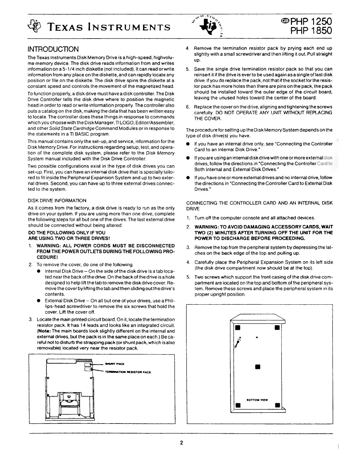
4.
Carefully piace
the
Peripheral Expansion
System
on its left side
(lhe
disk
drive
compartment
now
should
beat
the top).
5.
Two screws
which
support
the front
casing
of the
disk
drive
com-
partment are located o n the
top
and
botto
m
of
the
peripheral
sys-
tem. Remove these
screws
and
piace the peripheral system in ils
proper
upright
position.
•
•
.
l
•
BOTTOM
VIEW
•
•
 Loading...


