6.
Remove the front casing
lrom
the
opening
ol
the
disk
drive
com-
partment.
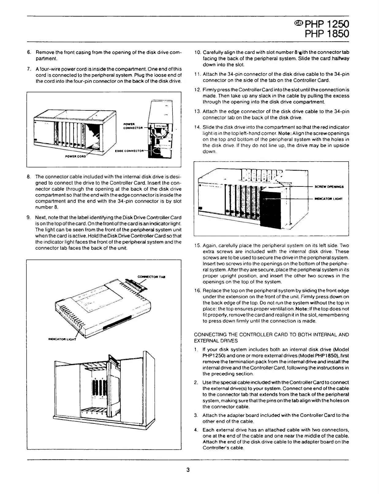
7.
A
lour-wire
power
cord
is inside
the
compartment. O
ne
end
ol
this
cord
is
connected
lo
the peripheral system. Plug the
loose
end
ol
the
cord
into the
lour-pin
connector
o n the
back
of
the
disk
drive.
I'OWU
COIIIHECTOJI
-..-_,._..-
8.
The
connector
cab
le
included
wilh
the internai
disk
drive is
desi-
gned to
connect
the
drive to the Controller Card. lnsert the
con-
nector
cable
lhrough
the
opening
al
the
back
ol
the
disk
drive
compartment
so that the end with
!h
e
edge
connector
is inside !h e
compartment
and the end with
the
34-pin
connector
is
by
slot
number
8.
9.
Ne xl,
note
!hai
!h
e label identifying
!h
e
Disk
Drive ControUer Card
iso
n the top
ol
the card. O n the front
ol
the
card
is an
indicator
light.
The light can be seen from the front
ol
the
peripheral
system uni!
when
the card is active.
Hold
the
Disk
Drive
Controller
Card so that
the
indicator
light
laces
the
front
ol
the peripheral
system
and the
connector
tab
laces
the
back
ol
the
unii.
CONNECTOR
TA8
3
<m>
PHP
1250
PHP
1850
1
O.
Carelully align the
card
with slot
number
8 with
the
connector
tab
facing the
back
ol
the peripheral system.
Slide
the
card
halfway
down
into the slot.
11. Attach the
34-pin
connector
ol
the
disk
drive
cable
lo
the
34-pin
connector
on the side
ol
the
!ab
on
the
Controller
Card.
12. Firmly press the
ControllerCard
in
lo
the slot unti l
!h
e
connection
is
made. Then take
up
any
slack
in the
cable
by
pulling the
excess
through the opening into the
disk
drive
compartment.
13. Attach the edge
connector
ol
the
disk
drive
cable
to the
34-pin
connector
tab on
lhe
back
ol
the
disk
drive.
14.
Slide the
disk
drive into the
compartment
so that
the
red
indicator
light is in the top left-hand corner.
Note:
Align the
screwopenings
on the top and bottom
ol
thc peripheral systcm with
the
holes
in
thc
disk
drive. lf
thcy
do
not line up, the drive
may
be
in
upside
down.
----------·-·----~~--------
15. Again, carefully piace the peripheral system on its left side. Two
extra screws are
included
with the internai
disk
drive. These
screws are to be used
lo
secure
the
drive
in
the
peripheral system.
lnsert
two screws into the
openings
on the
botto
m of the
periphe-
ral system. Alter they are secure,
piace
the
peripheral system in its
proper
upright position, and insert
the
other
two
screws
in the
openings
on the top
ol
the system.
16. Replace
!h
e top o n
!h
e peripheral system
by
sliding
!h
e front
edge
under
the extension on the
lront
of the unii. Firmly
press
down
on
!h e
back
edge of !h e top. Do no! run
the
system
without
the
top
in
piace: the top ensures pro per ventilation.
Note:
Il the top
does
noi
fil properly, rcmove l h e card and realign il in l h e slol, remembering
lo
press
down
firmly unti l the
connection
is made.
CONNECTlNG
THE
CONTROLLER CARD
TO
BOTH INTERNAL AND
EXTERNAL
DRIVES
1.
Il
your
disk
system
includes
both
an internai
disk
drive (Model
PHP1250) and one
or
more external drives (Model PHP1850), lirst
remove the terminalion
pack
lrom
the internai drive
and
installthe
internai drive and l h e
Controller
Card,
lollowing
the
instructions
in
the
preceding
section.
2.
Use the special cabte
included
with the
ControllerCard
lo
connect
the external drive(s)
lo
your
system.
Connect
one
end
of
!h
e
cable
lo
the
connector
!ab
that
extends
from !h e
back
of
!h
e peripheral
system, making su re
!hai
!h e
pins
on
!h
e tab align
with
!h
e
ho
l es
on
the
connector
cable.
3.
Attach the adapter board
included
with
!h
e
Controller
Card
!o !h
e
other
end
of !h e cable.
4.
Each external drive has an
attached
cable
with
two
connectors,
one at the end of the cable and one near the
middle
of
the
cable.
Atlach the end of the
disk
drive
cab
le t o the
adapter
board
o n the
Controller's cable.
 Loading...


