I2C
Signal Traces Connecting
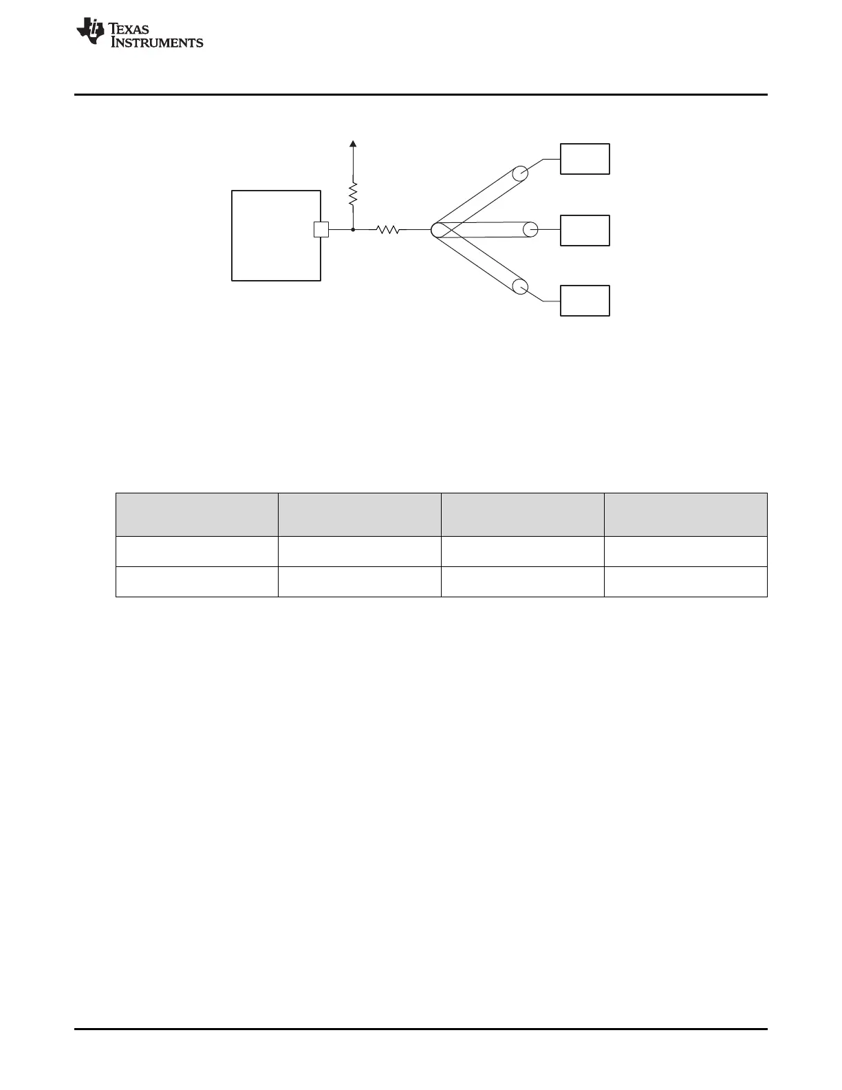
Other I2C Devices
V
DDIO
R
pu
R
st
SCL
SDA
MCU
I2C
I2C
www.ti.com
Usage Notes and Known Design Exceptions to Functional Specifications
35
SPRZ412K–December 2013–Revised February 2020
Submit Documentation Feedback
Copyright © 2013–2020, Texas Instruments Incorporated
TMS320F2837xD Dual-Core MCUs Silicon Revisions C, B, A, 0
Figure 7. Placement of Series Termination Resistor and Pullup Resistor
Table 7 provides series termination and pullup resistor value recommendations. The I2C
signal level and respective V
DDIO
power supply voltage is shown in the first column. Two
resistor value combination options are provided for each voltage. One option supports a
maximum high-level input current of 200 uA to all attached I2C devices, while the other
option supports a maximum high-level input current of 100 uA to all attached I2C
devices.
Table 7. Recommended Values for Series Termination Resistor and Pullup Resistor
I2C SIGNAL LEVEL AND
RESPECTIVE V
DDIO
POWER SUPPLY (V)
SERIES TERMINATION
RESISTOR (Ω)
PULLUP RESISTOR (Ω) NOTES
3.3 60 3300
Maximum high-level input
current up to 200 µA
3.3 75 6600
Maximum high-level input
current up to 100 µA
 Loading...


