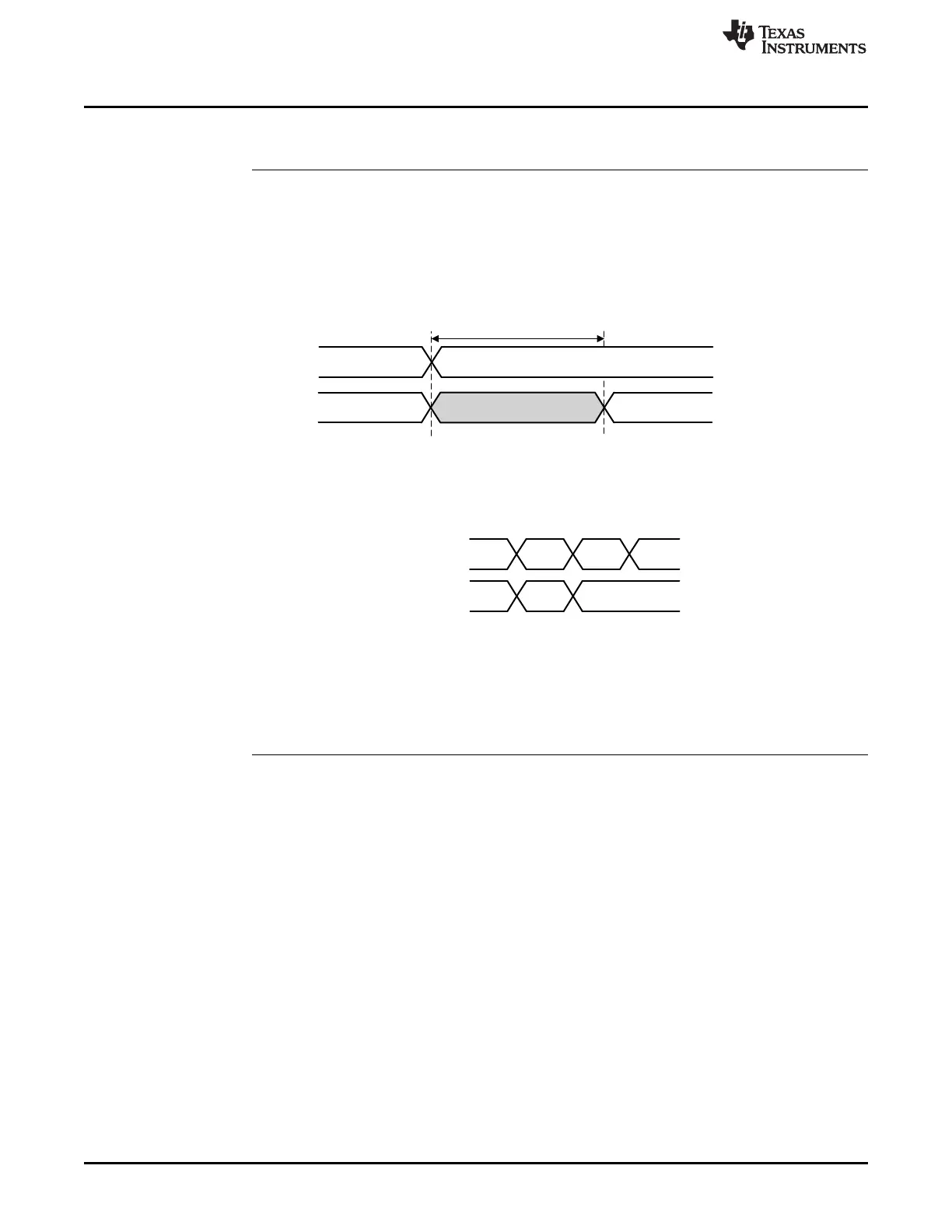
ePWM Output Pin (Possibility A)
(Trip interrupt will be issued)
ePWM Output Pin (Possibility B)
(Trip interrupt will not be issued)
Active
State
Trip
State
Active
State
Trip
State
Active
State
Trip
State
Active State
Trip Active
Trip Source
Blanking Window
Blanking Window
Active
Undesired Trip
Active-to-Inactive Transition
Trip Inactive
Blanking Complete
3 ePWM cycles
Usage Notes and Known Design Exceptions to Functional Specifications
www.ti.com
36
SPRZ412K–December 2013–Revised February 2020
Submit Documentation Feedback
Copyright © 2013–2020, Texas Instruments Incorporated
TMS320F2837xD Dual-Core MCUs Silicon Revisions C, B, A, 0
Advisory ePWM: An ePWM Glitch can Occur if a Trip Remains Active at the End of the
Blanking Window
Revision(s) Affected 0, A, B, C
Details The blanking window is typically used to mask any PWM trip events during transitions
which would be false trips to the system. If an ePWM trip event remains active for less
than three ePWM clocks after the end of the blanking window cycles, there can be an
undesired glitch at the ePWM output.
Figure 8 illustrates the time period which could result in an undesired ePWM output.
Figure 8. Undesired Trip Event and Blanking Window Expiration
Figure 9 illustrates the two potential ePWM outputs possible if the trip event ends within
1 cycle before or 3 cycles after the blanking window closes.
Figure 9. Resulting Undesired ePWM Outputs Possible
Workaround(s) Extend or reduce the blanking window to avoid any undesired trip action.
Advisory ePWM: ePWM Dead-Band Delay Value Cannot be Set to 0 When Using Shadow
Load Mode for RED/FED
Revision(s) Affected 0, A, B, C
Details ePWM dead-band delay value cannot be set to 0 when using Shadow Load Mode for
rising-edge delay (RED) and falling-edge delay (FED).
Workaround(s)
1. Use Immediate Load Mode if DBRED/DBFED = 0.
2. Do not use DBRED/DBFED = 0 if in Shadow Load Mode.
This is for both RED and FED.
 Loading...


