Speech Dialler Installation Manual
INS232-2 7
Connections to the Control Panel
Before making any connections to the unit, isolate ALL power from the control
panel (AC mains and battery). Do not continue if there is power still present on the
control panel.
+12V & 0V: These terminals must be connected to the 12V auxiliary power supply of
the alarm control panel.
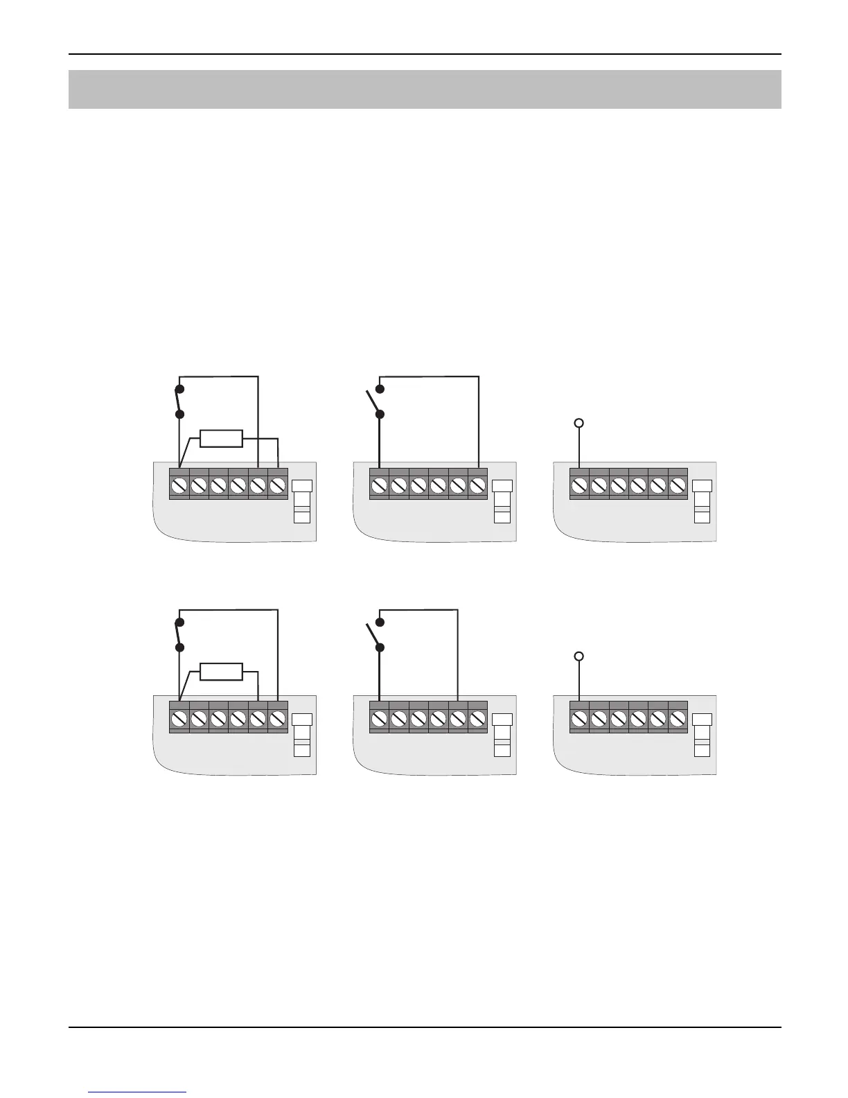
Trigger 1 - 4: These terminals should be connected to the relevant outputs on the
alarm control panel. When the input is triggered the dialler will initiate the calling
sequence and play the relevant speech and/or text message. The diagram below
show the various wiring options for the trigger inputs:
N.C.
Loop
1
23
4
0V
12V
Trigger Inputs
1KW
N.O.
Loop
1
23
4
0V
12V
Trigger Inputs
+12V when active
(+ve applied)
1
23
4
0V
12V
Trigger Inputs
Trigger Inputs programmed for +ve operation
N.C.
Loop
1
23
4
0V
12V
Trigger Inputs
1KW
N.O.
Loop
1
23
4
0V
12V
Trigger Inputs
0V when active
(+ve removed)
1
23
4
0V
12V
Trigger Inputs
Trigger Inputs programmed for -ve operation
Tamp: These terminals provide tamper protection for the dialler and should be
connected to the auxiliary tamper circuit on the alarm control panel.
OP1 & OP2: Two programmable switched –ve @100mA outputs.
Mic: A Texecom Remote Microphone Module can be connected to this input, to
enhance the listen-in mode.
 Loading...