Speech Dialler Installation Manual
6 INS232-2
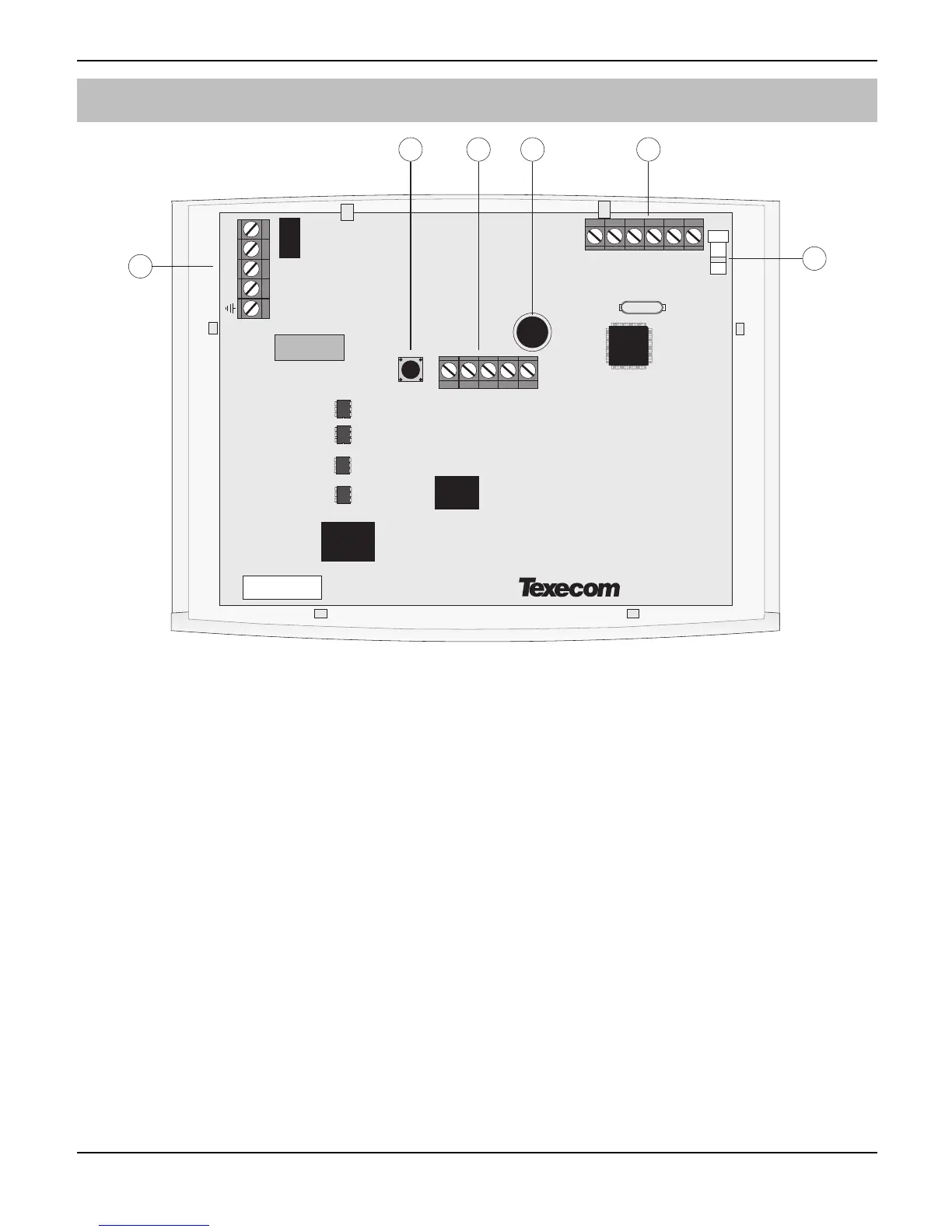
PCB Layout
OP1-
Tamp
1
2
6
4
OP2-
1
23
4
0V
12V
Trigger Inputs
R1 T1 R T
3 5
Mic
$
Telephone connections (TNV)
%
Tamper switch
&
Programmable outputs, tamper and remote microphone connections (SELV)
'
Microphone
(
Trigger Inputs and power supply connections (SELV)
)
Loudspeaker connector (SELV)
Connection terminals on the dialler are described as either “Safety Extra Low Voltage”
circuits (SELV) or “Telecommunications Network Voltage” circuits (TNV).
• It is important that the TNV connections are only connected to the PSTN, and
SELV circuits are only connected to other circuits designated as SELV circuits.
• Interconnection circuits should be such that the equipment continues to comply
with the requirements of 4.2 of EN 41003 for TNV circuits and 2.3 of EN 60950
for SELV circuits, after making connections between circuits.
 Loading...