McCAULEYPROPELLERSYSTEMS
CONSTANTSPEEDCOMPOSITEOWNER/OPERATOR
INFORMATIONMANUAL
(4)Removeallresidualcement,edgesealerandepoxyfromtheblade.Usesolventswithcaution
asmentionedabove.
(5)Visuallyinspectthepropellerbladefordamageordeterioration.Checkfordelamination,cracks,
dentsornicks.Ifdefectsarefound,thepropellermustberepairedbyanauthorizedpropeller
repairstation.
B.PropellerDeiceBootInstallation.
(1)Theseinstructionsdescribetheprocedurestobefollowedfortheinstallationofelectrothermal
propellerdeicebootsonMcCauleypropellerblades.
CAUTION:Theconditionofthepropellerbladesandthedeicebootinstallation
mustcomplywithapplicableFAAregulations.Inspecteach
propellerbladepriortodeicebootinstallationforanydelamination,
cracks,dents,ornicks.Ifanydefectsarefound,theblademustbe
repairedbyanFAAapprovedPart145PropellerRepairStationor
internationalequivalentbypersonneltrainedtorepairMcCauley
compositepropellercomponentspriortotheinstallationofthe
deiceboot.Checkresistanceofeachheatingelementbefore
installationofthedeiceboot.RefertoTable202fordeiceboot
resistancevalues.
(2)Alldeicebootsonasinglepropellermustbelocatedthesamedistancefromthecenterline
ofthepropellerforrotationalbalance.The("Y")dimensionforthelocationofthedeicebootis
giveninT able201andshowninFigure202.
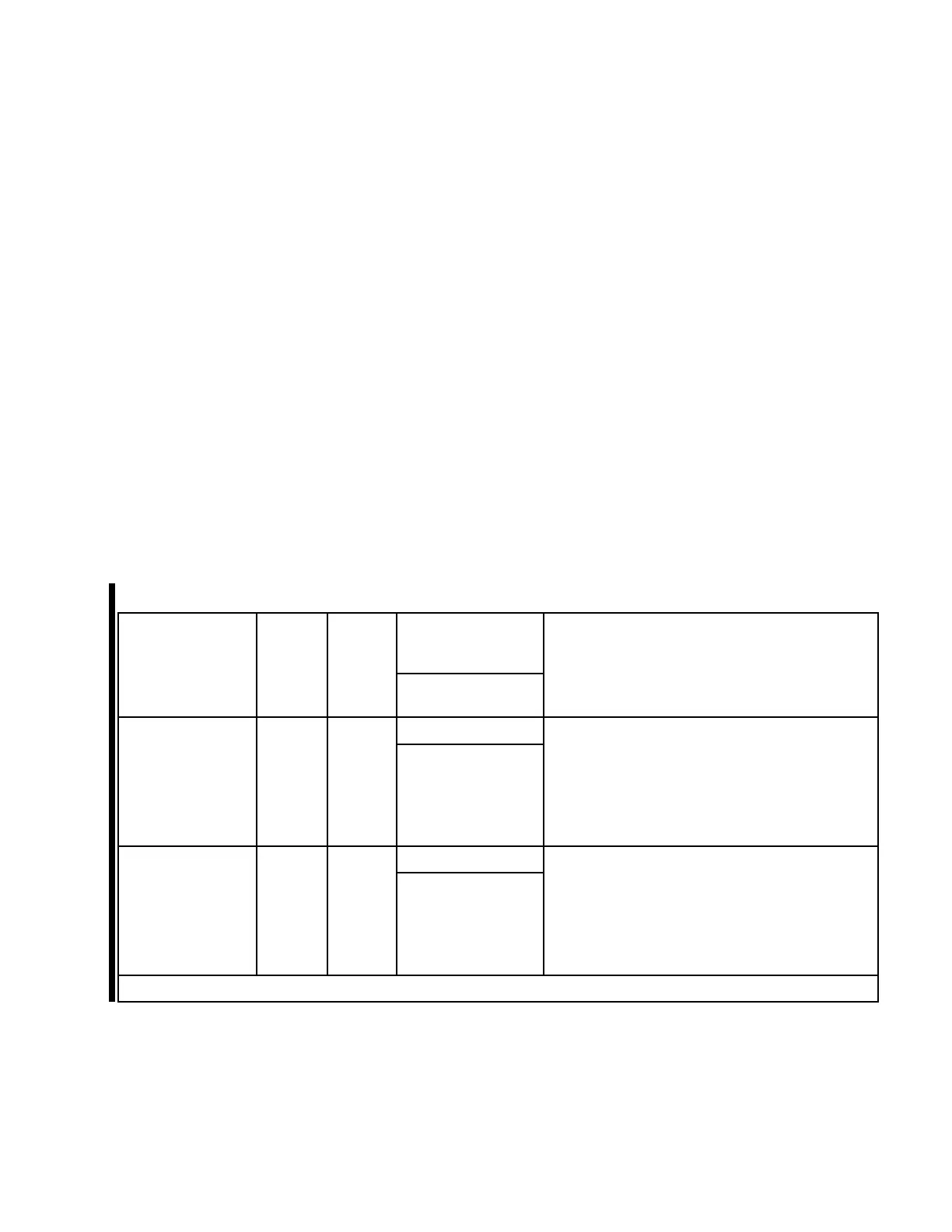
Table201.AircraftandSystemIdenticationandInformation
McCauley
PropellerModel
No.
NormalTotal
NominalPower
(Watts)
Dim
"Y"
See
Note1
Dim
"X"
See
Note1
DeiceBootPart
No.Notes
D3A37C3401
120*
1.302to
1.428
Inch(
36.27
to33.07
mm)
0.187
to
0.313
Inch
(4.75
to7.95
mm).
B-40746-30
3bladeprop,integralleads,singleengine,
singleelement,28VDCdeicebootheating
element.
D3A37C3401
120**
1.302to
1.428
Inch(
36.27
to33.07
mm)
0.187
to
0.313
Inch
(4.75
to7.95
mm).
B-40746-31
3bladeprop,integralleads,singleengine,
singleelement,14VDCdeicebootheating
element.
*Basedon24to28VDCatdeicebootleads.
61-03-00Page206
©McCauleyPropellerSystemsJan9/2017