McCAULEYPROPELLERSYSTEMS
CONSTANTSPEEDCOMPOSITEOWNER/OPERATOR
INFORMATIONMANUAL
(7)Visuallydoaninspectionofthepropellerbladefordamageordeterioration.Lookforcracks,
delamination,dentsornicks.Ifpropellerbladedamageisfound,thepropellermustberepaired
byanauthorizedpropellerrepairstation.
B.InstalltheAnti-icePropellerFeedShoes(RefertoFigure201).
(1)General.
(a)Allanti-icefeedshoesonasinglepropellermustbelocatedthesamedistancefromthe
centerlineofthepropellerforrotationalbalance.The("W")dimensionforthelocationof
theanti-iceshoeisgiveninTable202andshowninFigure201.
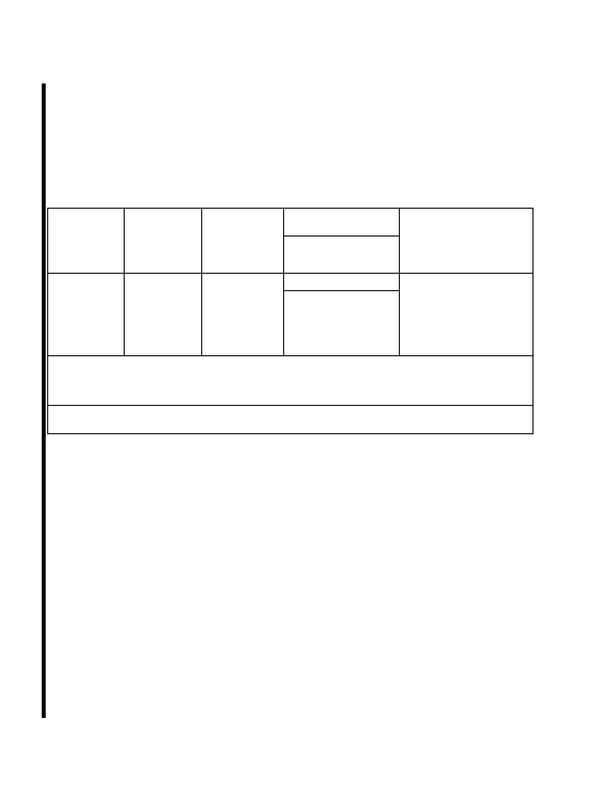
Table202.AircraftandSystemIdenticationandInformation
McCauleyPropeller
ModelNo.
AircraftMake
andModelNo.
ShoePart
Number
Dimension"W"
SeeNote2
McCauleyPropeller
PartNo.NotesSeeNote1
D3A37C3401
CessnaT240
CorvalisTTx
C-40323-81
2.428to2.302
Inches(61.67to
58.47mm)
P34017898-0381
AirplaneTKSnozzleto
propellerslingerring
minimumclearanceis
0.05inch(1.3mm)minimum
and0.15inch(3.8mm)
maximumforwardofthe
rearedgeoftheslingerring.
NOTE1:McCauleypropellerssometimesareprovidedtotheaircraftmanufacturerwithouttheanti-iceshoes
installed.Incaseswheretheaircraftmanufacturerinstallstheanti-iceshoes,orwherenoMcCauleyanti-ice
shoesareused,theappropriateaircraftmanufacturer'sservicemanualorsupplementaltypecerticate
mustbeconsultedforallinstallationinformation.
NOTE2:Anti-IceShoeLocationDimension"W"(Distancefromthepropellerbladeretainingringtothestart
ofthefeedshoecentergroove.)SeeFigure201.
(2)PreparethePropellerBladesfortheFeedShoeInstallation.
(a)Withtheinboardendoftheanti-icefeedshoelocatedatDimension"W",positionthefeed
shoeoverthepropellerbladeleadingedge.
(b)Makesurethepropellerisatlowpitch.
(c)Aligntheinboardendofthefeedshoe,centeroftherstgrooveintheanti-icefeedshoe
(rstgrooveofthefeedshoefromthepropellerleadingedgetothecambersideofthe
propellerblade)withthecenterlineoftheanti-icefeedtube.
(d)Aligntheoutboardendofthefeedshoe,tothepropellerbladesothatthefeedshoecenter
lineisontheleadingedgecenterlineofthepropellerblade.
(e)Markanarea0.5inch(12.70mm)outsidethefeedshoeperimeteronthepropellerblade
witharedpencil.
(f)Usetheredpencillineastheperimeteroftheareaoneachpropellerbladetobemasked.
(g)Installmaskingtapearoundtheoutline.
CAUTION:Itisnecessarythatthemaskingstepsdescribedbefollowed
sothesealerwillbeappliedtoboththecementand0.125inch
(3.18mm)ofpropellerbladesurface.Ifthecementlineand
sealerlinestartatthesamepoint,waterwillseepunderthe
cementlineandcauseanunserviceableseal.
(h)Onpropellerbladespaintedwithpolyurethane,lightlysandinsidethemaskedoffareawith
400gritsandpaper.
NOTE:Ifthepropellerhasbeenpaintedwithalacquerbasepaint,carefullyremoveall
paintinsideofthemaskedoffareaoneachpropellerblade.
61-13-45Page204
©McCauleyPropellerSystemsJan9/2017