©Copyright Task Force Tips LLC 2002-2021 15 LIN-030 May 21, 2021 Rev18
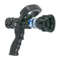
5.2 PATTERN CONTROL
TFT nozzles have full pattern control from straight stream to wide fog. Turning the stream shaper clockwise (as seen from the operating
position behind the nozzle) moves the shaper to the straight stream position. Turning the shaper counterclockwise will result in an
increasingly wider pattern.
Since the stream trim point varies with flow, the stream should be “trimmed” after changing the flow to obtain the straightest and farthest
reaching stream. To properly trim the stream, first open the pattern to narrow fog. Then close the stream to parallel to give maximum
reach. Turning the shaper further forward will cause stream crossover and reduce the effective reach of the nozzle.
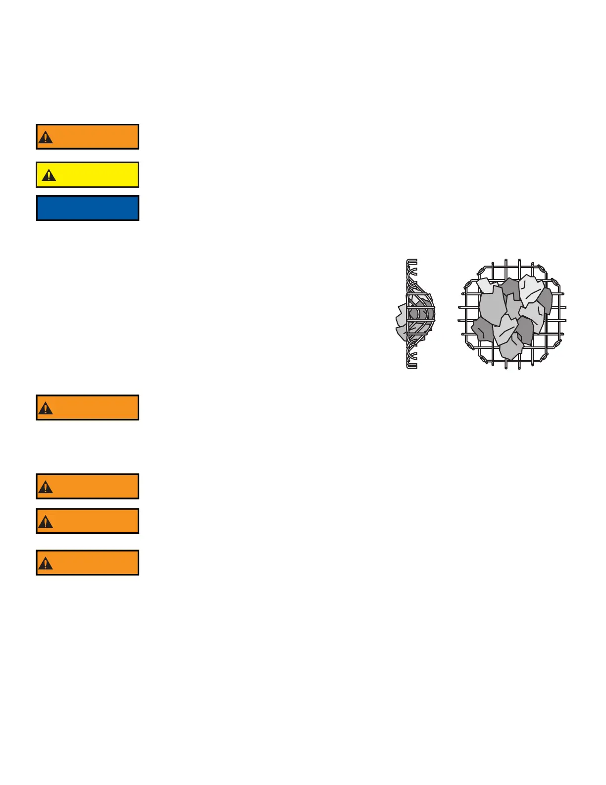
5.2.1 FLUSH CONTROL
Small debris passes through the debris screen (if so equipped) and may get caught
inside the nozzle. This trapped material will cause poor stream quality, shortened reach,
and reduced flow. To remove small debris, the nozzle may be flushed as follows:
• While still flowing water, rotate the shaper counterclockwise (as viewed from
behind the nozzle) to the flush position. (increased resistance will be felt on the
SHAPER as the nozzle goes into flush) This will open the nozzle allowing debris
to pass through.
• During flush the nozzle reaction will decrease as the pattern becomes wider and
the pressure drops. The nozzle operator must be prepared for an increase of
nozzle reaction when returning the nozzle from the flush position to retain
control of the nozzle.
• Rotate the shaper out of flush to continue normal operations.
6.0 USE WITH FOAM
The nozzle may be used with foam solutions. Refer to fire service training by the Authority Having Jurisdiction (AHJ) for the proper use
of foam.
6.1 FOAM ASPIRATING ATTACHMENTS
Multi-expansion or low expansion aspirating attachments may be used with nozzles to increase the expansion ratio. These foam tubes
attach and detach quickly from the nozzle. As expansion ratio is increased, the reach of the nozzle will decrease due to the greater
amount of bubbles in the stream and their ability to penetrate the air. Generally, the straight stream reach with foam is approximately
10% less than with water only. Actual results will vary based on brand of foam, hardness of water, temperature, etc. For specific
information, see LIA-025 (MANUAL: Foam Attachments for TFT Nozzles).
The nozzle reaction is greatest when the shaper is in the straight stream position. Sudden changes
in pattern can cause changes in reaction, leading to loss of footing or an out of control nozzle. The
nozzle operator must be prepared for a change in reaction as the pattern is changed.
CAUTION
Dents or nicks in the nozzle tip can seriously affect the stream reach or pattern, which may increase
the risk of injury due to exposure. Care must be taken to avoid dents or nicks in the nozzle tip.
Turning the shaper further forward will cause stream crossover and reduce the reach of the nozzle.
Large amounts or pieces of debris may be unflushable and can reduce the flow of the nozzle
resulting in an ineffective flow. In the event of a blockage, it may be necessary to retreat to a safe
area, uncouple the nozzle and remove debris.
For Class B fires, lack of foam or interruption in the foam stream can cause a break in the foam
blanket and greatly increase the risk of injury or death. Follow procedures established by the AHJ
for the specific fuel and conditions.
Improper use of foam or using the wrong type of foam can result in illness, injury, or damage to the
environment. Follow foam manufacturer’s instructions and fire service training as directed by the
AHJ.
Use of compressed air foam (CAF) with hand held nozzles can cause sudden surges in nozzle
reaction force resulting in risk of injury or death from loss of footing or hose whipping. Be prepared
for sudden changes in nozzle reaction caused by:
• Slug loading (Loss of foam concentrate sends slugs of air and water into the nozzle)
• Sudden release of built-up pressure in the hose when opening a nozzle
Figure 5.2.1