To this chapter contents
15. STEERING / FRONT SUSPENSION
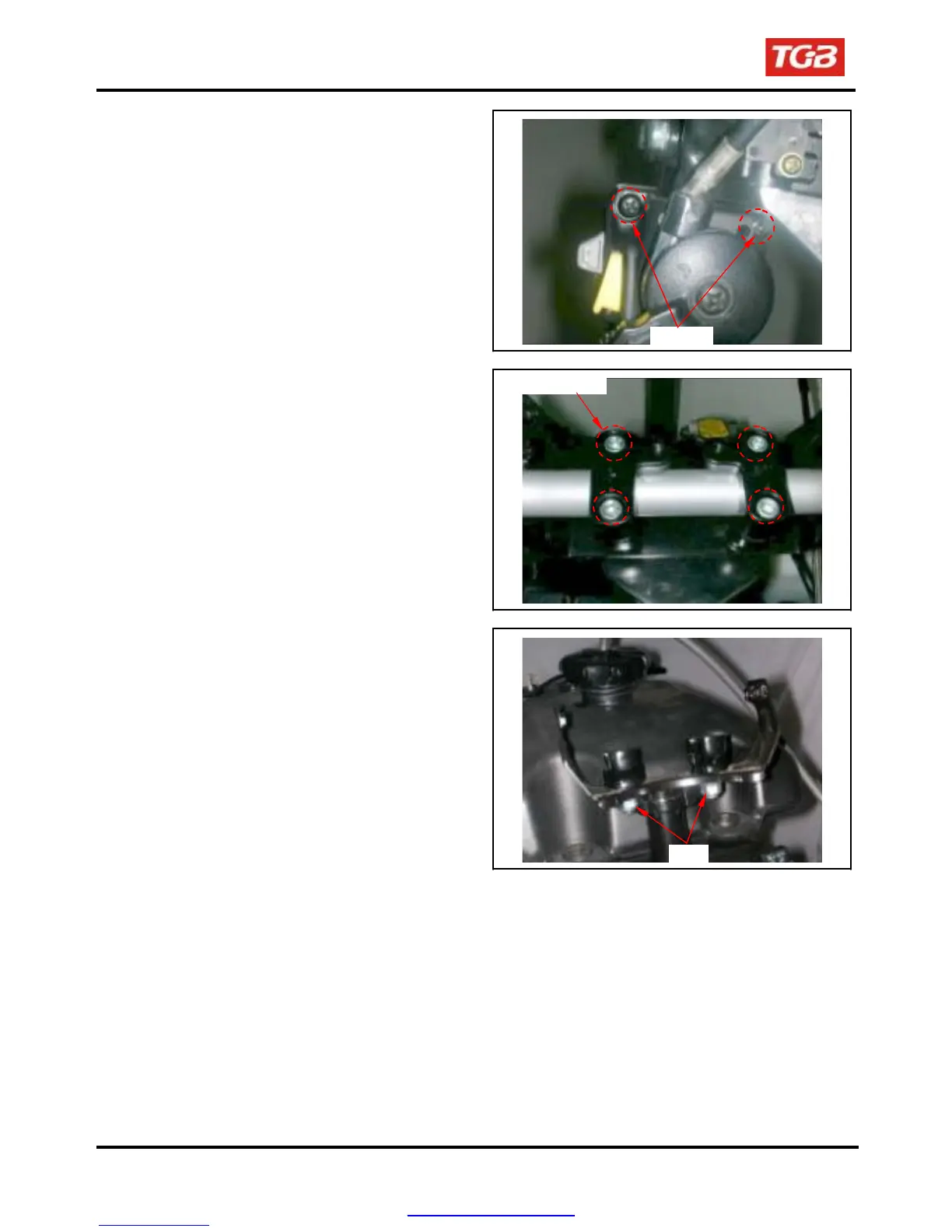
Loosen 2 screws, and then remove handle left
switch and choke hosing.
2 screws
Remove switch wire band.
Remove handle mounting bolt, and
then remove
the handle upper holder,
handle.
Remove 2 nuts to remove handle under holder
and meter bracket.
4 socket bolts
2 Nuts
Installation
Install in reverse order of removal procedures.
Torque value:
Handlebar under holder nut
4.0kgf-m
Handlebar upper holder bolt
2.4kgf-m
15-4
PDF created with pdfFactory Pro trial version www.pdffactory.com
 Loading...