To this chapter contents
17. ELECTRICAL SYSTEM
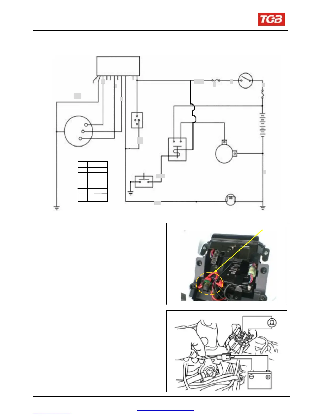
Starting System
Starting circuit diagram
C.D.I
W
B/W
Fuse 15A
B
Main switch
R
Main fuse
30A
F
N
R
G/Y
Brake
switch
Battery
Change switch
B1 Blue
B Black
R Red
G Green
W White
Y Yellow
BR Brown
Starter switch
Starter relay
Starter motor
G
G/Y
Brake light
Inspection on starter relay
Open the main switch.
Press the brake.
Push down the starter switch.
If a sound of “Looh Looh” is heard, it
indicates the
relay function normally.
Remove the seat.
Disconnect the negative cable terminal of the
battery.
Disconnect the cable positive terminal from the
relay.
Disconnect the positive cable of the starter motor.
Disconnect the coupler of the relay.
Connect an
ohmmeter to the large terminal end.
Connect the yellow/red cable to the battery positive
terminal and the black / blue cable to the battery
negative terminal.
Check the continuity of the large terminal end. If
there is no continuity, replace the relay.
Starter relay
BR/B
B1/W
R
B
B
PDF created with pdfFactory Pro trial version www.pdffactory.com
 Loading...