Cinterion
®
LGA DevKit User Guide
3 LGA DevKit Overview
35
t lga_devkit_ug_v03 2020-05-29
Public / Released
Page 10 of 36
3 LGA DevKit Overview
3.1 Top and Underside View
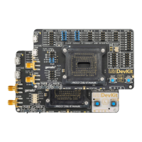
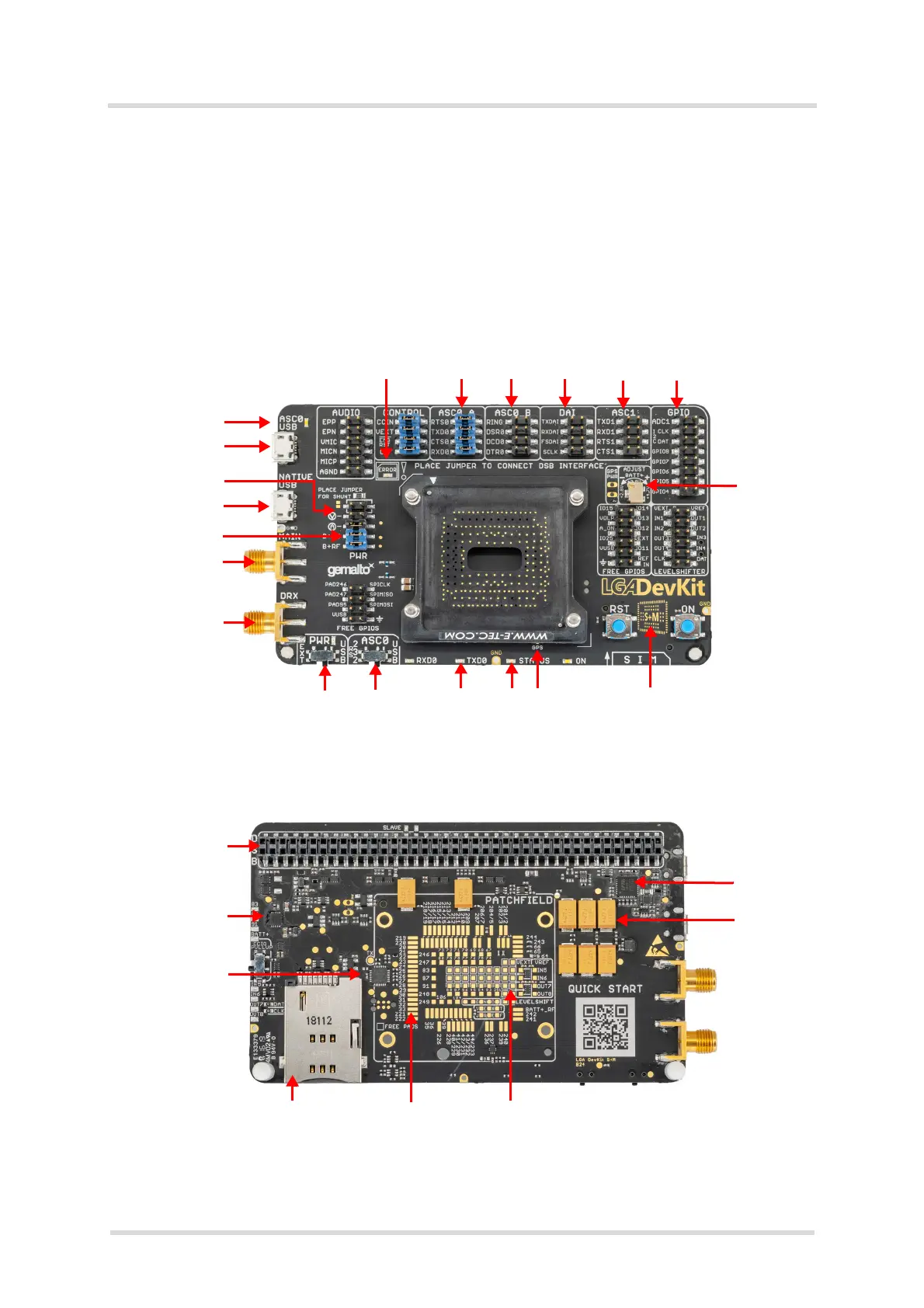
Figure 3 and Figure 4 show the top and underside view of the of the LGA DevKit SM variant.
Please note that both SM and L variants of the LGA DevKit are identical - except or the MAIN
and DIV antenna connectors that are interchanged, and the footprint indicators showing the dif-
ferent LGA module footprints.
Figure 3: LGA DevKit SM top view
Figure 4: LGA DevKit SM underside view
Error LED Configurable & interruptible signals
Adjustable
supply
Footprint indicator**
GPS
Activity LEDs
Channel select
Activity LED
USB VCP & PWR
Current test
USB & PWR
Supply mode
MAIN*
DIV*
* = MAIN and DIV antenna connectors are interchanged with the LGA DevKit L variant
** = Footprint indicator shows LGA156 footprint with the LGA DevKit L variant
DSB interface
PWR circuit
CTRL & Error det.
SIM
Module footprint ex. GND
Patch field
VCP FTDI
PWR buffer