Cinterion
®
LGA DevKit User Guide
4.11 RF Antenna
35
t lga_devkit_ug_v03 2020-05-29
Public / Released
Page 16 of 36
4.11 RF Antenna
The LGA DevKit supports three antenna interfaces. The two SMA connectors "MAIN" and
"DRX" are used for radio transmission. The GNSS interface is supported by an U.FL connector
named "GPS".
All antenna interfaces have additional ESD protection implemented.
The LGA DevKit package includes a broad band high efficiency PCB antenna that can be used
with the DevKit for all radio band combinations.
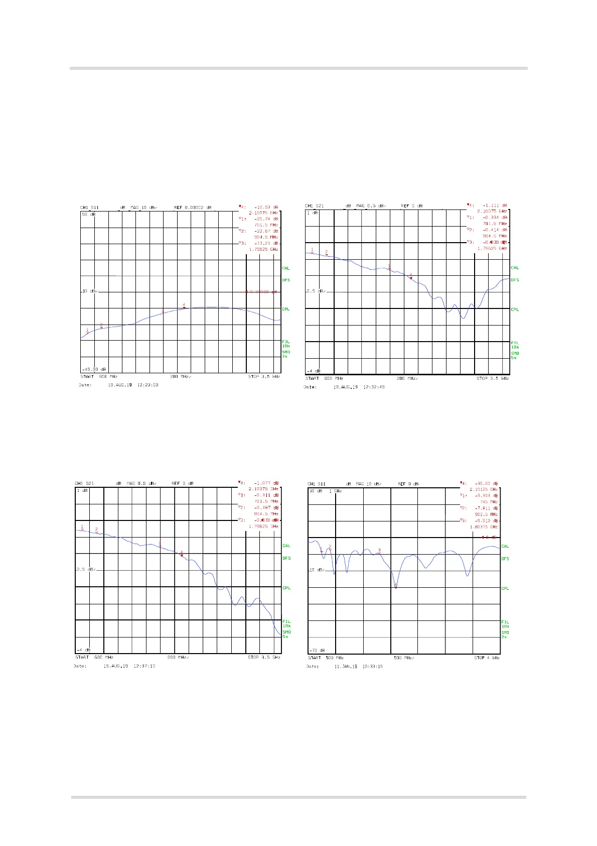
Figure 10: S11 MAIN antenna input return loss transmit
direction (with socket)
Figure 11: S21 MAIN antenna insertion loss transmit
direction (with socket)
Figure 12: S12 MAIN antenna insertion loss receive
direction (with socket)
Figure 13: Antenna S11