Cinterion
®
LGA DevKit User Guide
7 Module Specific Configuration Settings
35
t lga_devkit_ug_v03 2020-05-29
Public / Released
Page 22 of 36
7 Module Specific Configuration Settings
The following sections describe specific settings that must be taken into account for certain
modules.
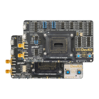
7.1 BGS1 and BGS2 Operation
BGS2 requires a reference voltage for the I/O domain at VDIG (pad 10 of the LGA106 foot-
print). Therefore please connect IO25 and VEXT via a jumper.
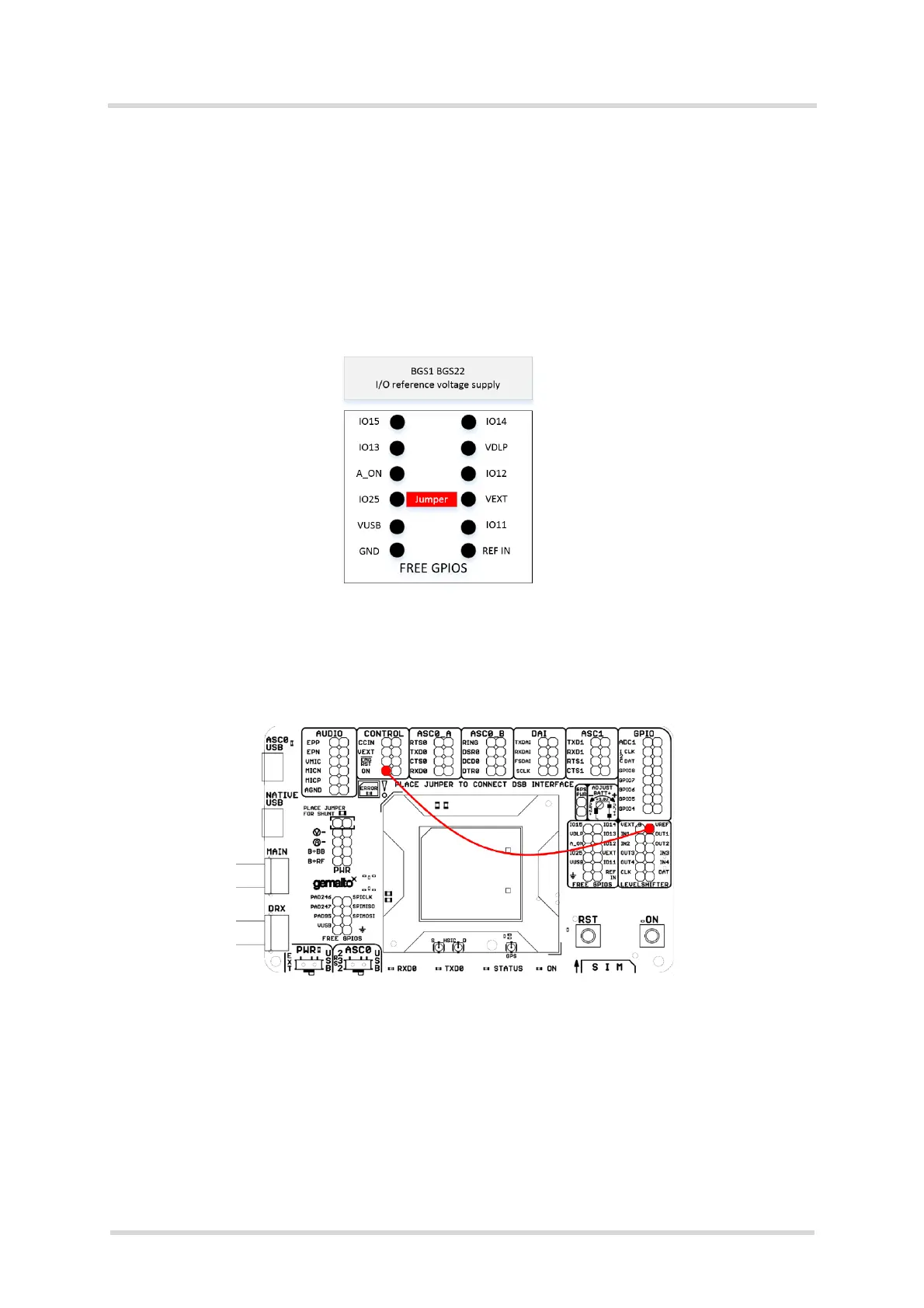
7.2 BGS12 Operation
For a proper start of BGS12 a connection between the module’s ON signal (in Control block)
and VREF (in level shifter block) is required.
7.3 EMS31 Operation
EMS31-V requires a pull up resistor for the SIM interface that is not automatically detected as
with other modules. In order to activate the SIM pull up please use the SIM switch setting on
the LGA DevKit’s underside as described in Section 4.2.