Manual 0-2972 5-3 REPLACEMENT PROCEDURES
B. ON/OFF Switch (SW1) Replacement
1. Remove the power supply cover per Subsection
5.04-A.
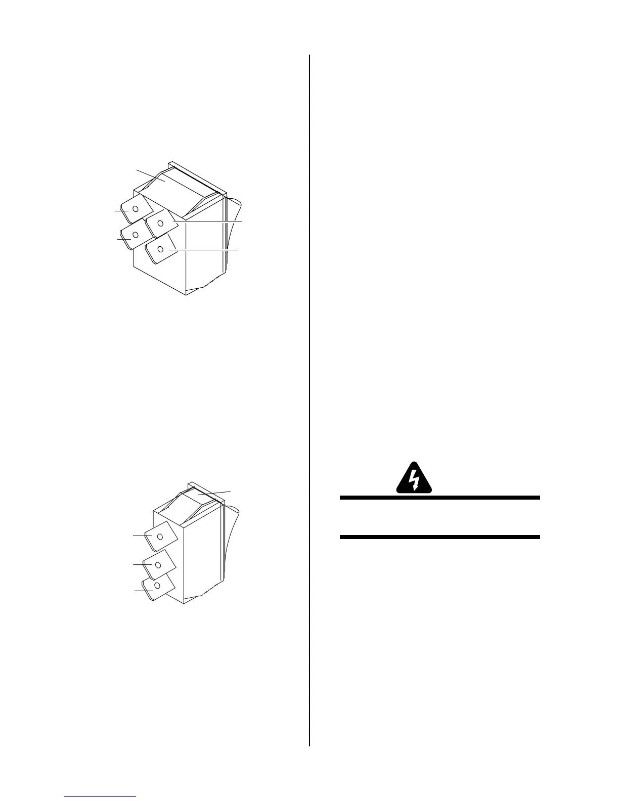
2. Disconnect the wires on the rear of the Switch, not-
ing the location and orientation of each wire as
shown below:
Art # A-02774
Wire #21
Wire #24
Top clip
Wire #22
Wire #23
3. Squeeze together the clips on the rear of the Switch,
then remove the Switch through the Front Panel.
4. Install the replacement Switch by reversing the
above steps.
C. RUN / RAPID AUTO RESTART / SET
Switch (SW2) Replacement
1. Remove the cover per Subsection 5.04-A.
2. Disconnect the wires on the rear of the Switch, not-
ing the location and orientation of each wire as
shown below:
Art # A-03906
Wire #25
Wire #26
Top clip
Wire #46
3. Squeeze together the clips on the rear of the Switch,
then remove the switch through the Front Panel.
4. Install the replacement switch by reversing the
above steps.
5. Reinstall the power supply cover.
D. POT/LED PC Board Replacement
Follow the antistatic procedures in Subsection 5.02.
1. Remove the cover per Subsection 5.04-A.
2. Remove Current Knob per procedures in Subsec-
tion 5.05-A.
3. Disconnect J Connector from POT/LED PC Board.
4. Remove PC Board from standoffs.
5. Install the replacement POT/LED PC Board by re-
versing the above steps.
E. Work Cable Replacement
1. Remove the cover per Subsection 5.04-A.
2. Disconnect the Work Cable from the WORK termi-
nal on the Main Power PC Board, located on the left
side of the unit.
3. Squeeze the top and bottom of the Work Cable Strain
Relief and remove from the Front Panel.
4. Remove Work Cable from the unit.
5. Install the replacement Work Cable by reversing
the above steps.
5.06 Left Side Internal Parts
Replacement
Refer to Subsection 6.05 Left Side Internal Replacement
Parts.
WARNING
Disconnect primary power from the source before
opening or disassembling the power supply.
A. Fuse Replacement
1. Remove the cover per Subsection 5.04-A.
2. Locate the Fuse near the top edge of the Main Power
PC Board and remove the Fuse.
3. Install replacement fuse.
4. Reinstall the power supply cover.
 Loading...


