Manual 0-2859 3-7 INSTALLATION PROCEDURES
C. Machine Systems (Shielded Leads)
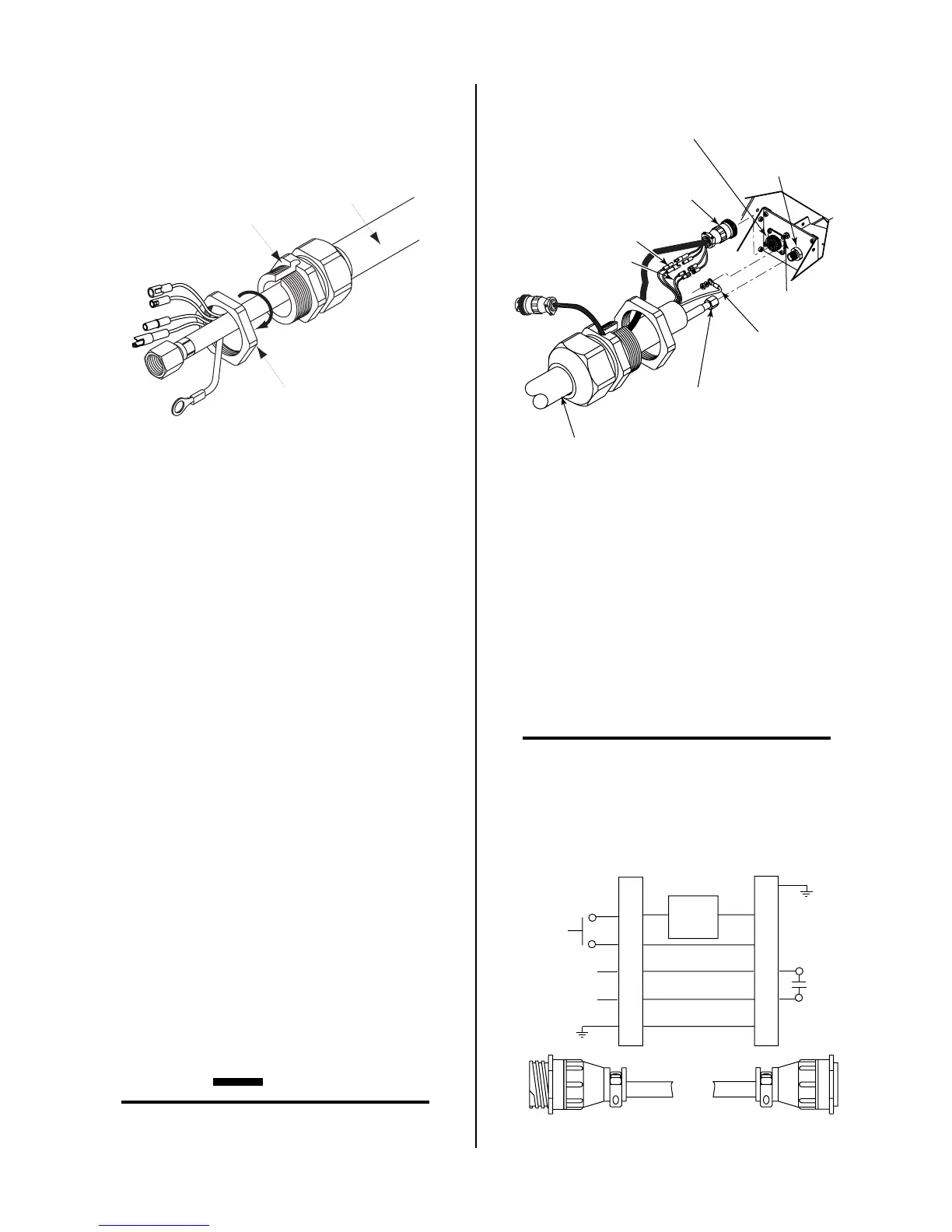
1. Remove the Strain Relief Nut from the Strain Re-
lief.
Strain Relief
Nut
Strain Relief
Torch Leads
Assembly
A-02826
Strain Relief Nut Removal
2. Install the Adapter supplied with the Power Sup-
ply as follows:
a. Inside the Power Supply Bulkhead area, route
the connector on the free end of the Adapter
through the Strain Relief Nut.
b. Continue routing the connector out the hole
in the front of the Power Supply.
c. Feed the end of the torch lead and the Strain Relief
into the hole in the unit while routing the single
black wire into the notch of the Strain Relief.
d. Tighten the Strain Relief Nut to secure the
Strain Relief to the Power Supply.
3. Connect the torch Negative/Plasma Lead to the
bulkhead connection inside the Power Supply.
4. Connect the PIP and Shield Cables to the mating
connectors on the Adapter supplied on the Power
Supply.
5. Remove the top nut and washer from the Pilot
Stud.
6. Place the lug on the Pilot Control Wire onto the
stud and secure with the nut and washer removed
in the above Step.
7. Tighten the Strain Relief onto the Torch Leads.
8. Check the torch for proper parts assembly.
CAUTION
The torch parts must correspond with the type of
operation. Refer to Section 4.04-A, Torch Parts
Selection.
Adapter
(Supplied With
Power Supply)
Pilot Lead
Torch Lead
Assembly
Negative/Plasma
Lead
Adapter Connector
Pilot Lead
Stud
Negative/Plasma
Lead Connection
A-02829
Control (PIP) Circuit
Connectors
Shield Connectors
Torch Lead Connections
D. Remote Pendant Control (Optional)
In machine type operations the Power Supply has an
Adapter that has a cable connector. The remote pen-
dant lead connector allows connection to a remote
pendant or CNC cable while using Control Circuit
connections in the Torch Assembly.
Connect the remote pendant control cable to the connec-
tor provided on the Adapter from the Power Supply.
NOTE
Refer to Appendix 3, Torch Control Cable Wiring
Diagram For Mechanized Systems, for detailed
schematic of the Adapter.
2
3
4
12
14
13
Torch Control
Cable Connector
Remote Pendant
Cable Connector
PIP
Circuit
Control
3
4
12
14
13
A-03102
Remote Pendant Connector Diagram
 Loading...


