Do you have a question about the Thermal Dynamics PAK Master 150XL and is the answer not in the manual?
Explains how notes, cautions, and warnings are categorized and used in the manual for highlighting important information.
Details critical safety measures for operating and maintaining plasma arc equipment, covering gases, fumes, electric shock, fire, noise, and arc rays.
Lists relevant safety standards and publications for further reference on workplace safety.
States that the equipment conforms to applicable European and National directives and standards.
Outlines the limited warranty terms, coverage, and limitations for Thermal Dynamics products.
Outlines the manual's purpose, content, and restrictions on service personnel for the PAK Master 150XL.
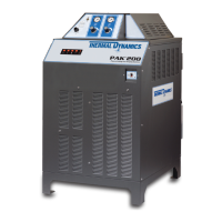
Provides a general overview of the plasma cutting power supply system, its capabilities, and typical configurations.
Details the technical specifications and design features of the power supply, including controls, inputs, and outputs.
Lists available options and accessories that can be purchased for the power supply system.
Introduces the installation section and its applicability to the Power Supply unit.
Guides on selecting an appropriate, well-ventilated, and safe location for the power supply.
Instructions for unpacking the equipment, checking the packing list, and inspecting for shipping damage.
Provides guidance on safely moving and lifting the power supply unit, including warnings.
Details electrical connections, local code compliance, and input power requirements for the unit.
Explains how to select and configure the correct input voltage for the power supply unit.
Provides step-by-step instructions for connecting the primary power cable to the power supply.
Describes how to connect plasma and secondary gas supplies to the power supply based on different gas types.
Provides instructions for connecting torch leads for various system configurations (Hand, Machine).
Details grounding procedures, including single point grounding, to minimize electromagnetic interference (EMI).
Step-by-step guide for filling the power supply with the correct coolant and purging air.
Introduces the operation section covering controls, indicators, and operating procedures.
Identifies and describes the function of the power supply's front and rear panel controls and indicators.
Details the step-by-step procedure for operating the plasma cutting system, from power on to shutdown.
Outlines essential pre-operation checks, including coolant level inspection.
Discusses factors affecting cut quality and characteristics of a good cut, including bevel angle and dross.
Provides general operational suggestions and safety reminders for cutting and gouging.
Explains how to configure optional settings via DIP switches for specialized applications.
Introduces the service section covering maintenance, troubleshooting, and repairs for operating personnel.
Covers routine maintenance tasks including cleaning the power supply and filter assemblies.
Lists common cutting problems and their probable causes, categorized by issue type.
Discusses common operational issues like piloting and torch standoff, and their remedies.
Provides a structured guide for diagnosing and resolving system issues, including AC power indicator faults.
Details procedures for replacing internal parts such as side panels and fuses.
Introduces the parts list breakdown and the procedure for returning products for service.
Provides guidance on how to order replacement parts, including required information.
Lists complete system configurations available for replacement, including power supply and torch options.
Lists replacement part numbers for the power supply unit itself, including voltage variants.
Lists common individual replacement parts such as fuses, filters, and coolant.
Lists available optional features and accessories for the power supply system.
Important notes regarding wiring requirements, cable de-rating, fuse types, and local code compliance.
Visual representation of the system's operational sequence and control flow from start to stop.
Illustrates the proper grounding arrangement for mechanized applications to minimize EMI.
Provides a schedule for daily, weekly, and periodic maintenance tasks for plasma cutting systems.
Shows the wiring diagram for the CNC interface connection between the cutting machine and power supply.
Detailed electrical schematic of the power supply unit, showing all components and connections.
| Input Voltage | 208/230/460 V |
|---|---|
| Input Frequency | 50/60 Hz |
| Open Circuit Voltage (OCV) | 300 VDC |
| Input Phase | 3 |
| Rated Input Current | 50/48/24 A |
| Output Current | 150 A |
| Duty Cycle | 60% @ 150 A |
| Gas Type | Air |
| Gas Flow | 190 lpm |