EasyManua.ls Logo

Thermal Dynamics SIGNATURE PAK 1250XRTM User Manual

Thermal Dynamics SIGNATURE PAK 1250XRTM
68 pages
To Next Page IconTo Next Page
Page #1 background imageLoading...
Page #1 background image
April 4, 2001 Manual No. 0-2377
PLASMA ARC
CUTTING SYSTEM
SIGNATURE
®
PAK
®
1250XR
TM
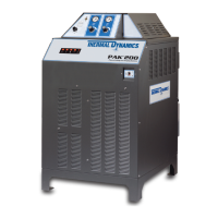
• PAK 1250 XR POWER SUPPLY
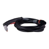
PCH/M-52 TORCH WITH WITH LEADS
WORK CABLE WITH CLAMP
TORCH SPARE PARTS KIT
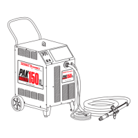
• RUNNING GEAR WITH HANDLE
• AIR LINE FILTER AND REGULATOR

Questions and Answers:

Thermal Dynamics SIGNATURE PAK 1250XRTM Specifications

General IconGeneral
ModelSIGNATURE PAK 1250XRTM
Input Frequency50 / 60 Hz
Gas Pressure90 - 120 psi (6.2 - 8.3 bar)
ProcessPlasma Cutting
TypePlasma Cutting System
Open Circuit Voltage (OCV)300V
Cutting Capacity (Mild Steel)1.5 inches (38mm)
Gas SupplyClean, dry, oil-free air or nitrogen
Gas TypeAir or Nitrogen
Cooling MethodAir Cooled

Summary

Section 1: System Description

1.1 General Description

Overview of the Plasma Arc Cutting/Gouging System.

1.2 Power Supply Specifications

Details on voltage, current, phase, and dimensions.

1.3 Torch Specifications

Torch configurations, lengths, current rating, and gas requirements.

1.5 Theory of Operation

Explains the principles of plasma gas flow and arc operation.

Section 2: Unit Assembly

2.1 Unpacking the System

Instructions for removing system components from packaging.

2.2 Equipment Assembly

Steps for assembling the running gear and handle.

2.3 Installation

Procedures for locating the unit and connecting gas and air lines.

2.4 Lifting the Power Supply

Safety precautions and methods for lifting the power supply unit.

Section 3: Operation

3.1 Operating Controls

Identification and function of controls on the PAK 1250 XR power supply.

3.2 Pre-Operation Set-up

Steps to prepare the system for operation, including torch and gas setup.

3.3 Cutting Operation

Detailed instructions for performing plasma arc cutting with a hand torch.

3.4 Gouging Operation

Instructions for performing plasma arc gouging operations.

3.6 Common Operating Problems

Lists common cutting problems and their probable causes.

3.7 Cutting Speeds

Charts showing optimal cutting speeds for various materials and gases.

3.8 Sequence of Operation

Step-by-step flow of system actions from startup to shutdown.

Section 4: Maintenance

4.1 Torch Maintenance

Procedures for inspecting and replacing torch consumable parts.

4.2 Torch Leads Replacement

Instructions for replacing torch leads for hand and machine torches.

4.3 Power Supply Maintenance

Maintenance tasks for the power supply, including fan lubrication and cleaning.

4.4 Troubleshooting Guide

Table of common problems, causes, and remedies for system malfunctions.

4.5 Test Procedures

Diagnostic tests for specific problems, including contactor and diode checks.

Section 5: Parts Lists

5.1 System Components & Accessories

Lists system components and optional accessories with catalog numbers.

5.2 Front Panel Components

Identifies components located on the front panel of the unit.

5.3 Rear Panel Components

Identifies components located on the rear panel of the unit.

5.4 Base Components

Lists components located in the base of the power supply unit.

5.7 Torch Components

Detailed list and diagrams of torch components.

5.8 Torch Accessories

Lists various accessories available for the torch.

5.9 Troubleshooting Diagram

A schematic diagram illustrating system operation and troubleshooting points.

5.11 Signature Pak 1250 XR System Schematic (Sheet 1)

First part of the system schematic diagram.

Signature Pak 1250 XR System Schematic (Sheet 2)

Second part of the system schematic diagram.

Related product manuals