27 SERVICE
4.1 TORCH MAINTENANCE
WARNING
Disconnect primary power to the system before
disassembling the torch, leads, or power supply.
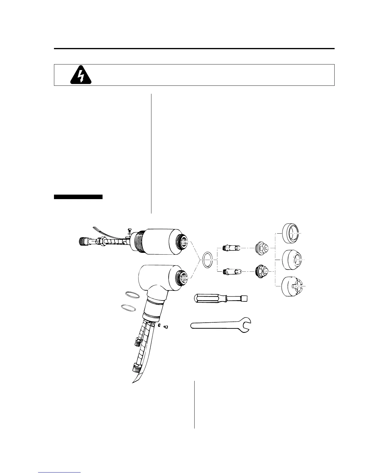
Figure 4-A Torch Components
Refer to Figure 4-A and:
1. Remove the shield cup (7) from the torch.
2. Unscrew the tip (6) using the tip wrench (8). Check for
tip wear (indicated by elongated or oversize orifice).
Clean the tip and make sure the threads and sealing
face are not damaged. Replace tip if necessary.
3. Remove the electrode (5) using the electrode wrench (9).
Inspect the condition of the face of the electrode
(see CAUTION below).
Check the torch for proper assembly. Tip and electrode
selection must correspond with the type of operation
(cutting or gouging, air or multi-gas). See Torch Parts
Selection, page 16).
If less than 1/8 in (3.2 mm) of the hex area on the front of
the electrode remains, the electrode should be replaced
(see Figure 4-B, page 28).
Routine Inspection
and Replacement of
Consumable Parts:
NOTE
CAUTION
6a. Gouging Tip
6b. Cutting Tip
7a. Gouging Shield Cup
7b. Standard Shield Cup
7c. Crown Shield Cup
8. Tip Wrench
9. Electrode Wrench
1. 180° Machine Torch Body
2. 70° Hand Torch Body
3. O-Ring (Handle)
4. O-Ring (Shield Cup)
5a. Multi-Gas Electrode
5b. Air Electrode
2
1
4
5b
5a
6b
6a
7b
7a
7c
8
9
3
A-01480
SECTION 4: MAINTENANCE
 Loading...