PARTS LISTS 6-6 Manual 0-2962
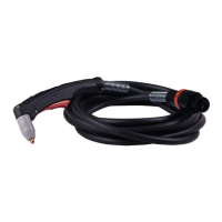
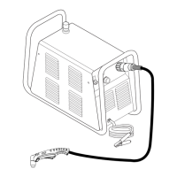
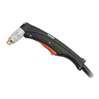
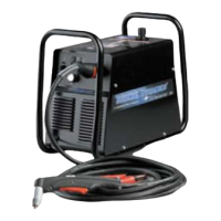
6.05 Replacement Shielded Machine Torch Leads Assemblies
Item No. Qty Description Catalog No.
1 Mechanized Shielded Leads Assemblies with ATC Connectors
1 5 - foot / 1.5 m Leads Assembly with ATC Connector 4-7846
1 10 - foot / 3.05 m Leads Assembly with ATC Connector 4-7847
1 25 - foot / 7.6 m Leads Assembly with ATC Connector 4-7848
1 50 - foot / 15.2 m Leads Assembly with ATC Connector 4-7849
2 Shielded Leads Assemblies with O2B Connectors
1 25 - foot / 7.6 m Leads Assembly with O2B Connector 4-7840
1 50 - foot / 15.2 m Leads Assembly with O2B Connector 4-7841
3 Negative / Plasma Lead
1 25 - foot / 7.6 m Length 9-7969
1 50 - foot / 15.2 m Length 9-7974
4 Shield Lead
1 25 - foot / 7.6 m Length 9-7979
1 50 - foot / 15.2 m Length 9-7980
5 PIP Lead
1 25 - foot / 7.6 m Length 9-7977 *
1 50 - foot / 15.2 m Length 9-7978 *
6 Pilot Lead, 25 - foot / 7.6 m Length
1 25 - foot / 7.6 m Length 9-7975
1 50 - foot / 15.2 m Length 9-7976
7 1 Power Supply Adapter for Shielded Leads (not shown) 7-3479
NOTE
*Does not include Torch continuity (PIP) Switch.

 Loading...


