EasyManuals Logo

Thermal Dynamics ULTRA-CUT 400 XT User Manual

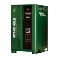
Thermal Dynamics ULTRA-CUT 400 XT
214 pages
To Next Page IconTo Next Page
To Previous Page IconTo Previous Page
Page #30 background imageLoading...
Page #30 background image
ULTRA-CUT 400 XT
3-4 INSTALLATION Manual 0-5275
3.05 Lift the Power Supply
WARNING
Do not touch live electrical parts.
Disconnect input power conductors from de-energized supply line before moving
unit.
FALLING EQUIPMENT can cause serious personal injury and equipment damage.
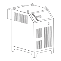
Use a forklift, crane, or hoist to lift the unit off the shipping pallet as shown. Keep the power supply steady and vertical. Do not
lift it any further than necessary to clear the shipping pallet. Ensure all panels and screws are secure prior to lifting.
Art # A-11531_AC
Set the power supply on a solid, level surface. The installer may fasten the power supply to the floor or a supporting fixture
with hardware passing through the horizontal parts of the power supply feet.

Table of Contents

Questions and Answers:

Question and Answer IconNeed help?

Do you have a question about the Thermal Dynamics ULTRA-CUT 400 XT and is the answer not in the manual?

Thermal Dynamics ULTRA-CUT 400 XT Specifications

General IconGeneral
Duty Cycle100% @ 400A
Output Current Range20-400 A
Open Circuit Voltage (OCV)300 V
Cutting Capacity (Recommended)1-1/2 in (38 mm)
Cutting Capacity (Maximum)2 in (51 mm)
Max Cutting Thickness5/8 in (16 mm)
Operating Temperature14°F to 104°F (-10°C to 40°C)
Gas TypeOxygen, Nitrogen, Air

Related product manuals