ULTRA-CUT 400 XT
6-2 REPLACEMENT PARTS Manual 0-5275
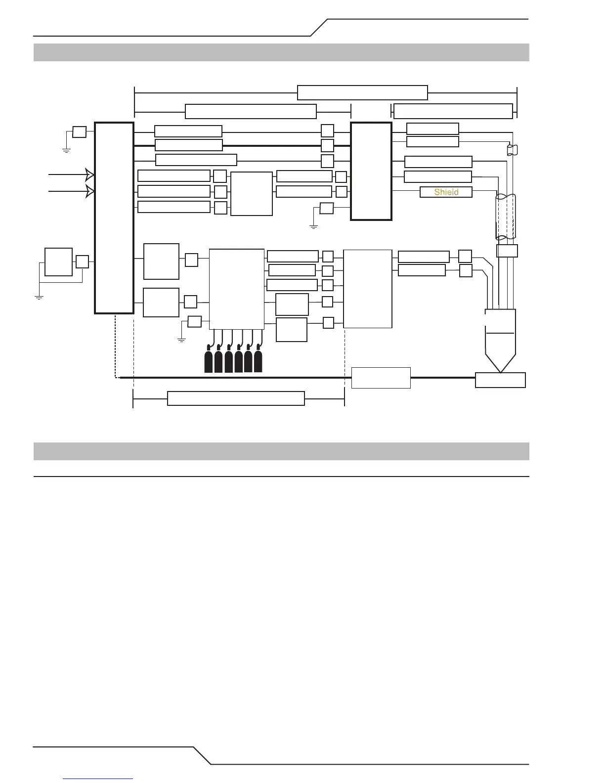
6.02 System Layout
Refer to section 3.05 for ground connections and ground cables.
CNC
Art # A-11940
Control
Cable
Fiber
Optic
Cable
Control
Cable
Gas Control
Module
Torch
Valve
Assembly
P
I
J
K
L
H
Q
R
S
Plasma Gas
Shield Gas
Plasma Gas
Shield Gas
Preflow Gas
Work
Torch
Positioning Tube
Water
Shield
G
T
Work Cable
175’ / 53.3 m Maximum Length
Primary power
Remote
Arc
Starter
Coolant Supply 10’
Coolant Return 10’
Control Cable
Pilot Return
Coolant Supply
Coolant Return
Ultra-Cut
XT Power
Supply
Shield
Negative Cable
Pilot Return #8
50’ / 15.25 m Maximum Length
Shield
A
B
E
C
D
125’ / 38.1 m Maximum Length
175’ / 53.3 m Maximum Length
F1
F1
HE 400
Heat
Exchanger
Control Cable
C
D
Y
Coolant Supply
Coolant Return
F
6.03 Recommended Gas Supply Hose
Item # Qty Description Catalog #
1 3/8”Gray Synflex Hose. No fittings included. Catalog number per foot 9-3616

 Loading...


