藍色線條為尺寸標示,請勿印刷上去!
190 mm
266 mm
刀模線
產品料號
CA-1J9-00F9WN-00 Level 20
說明書
18/04/11
A
產品名稱
印刷項目
發稿日期
版本
CHECK DESIGN
Dora
(18/04/11)
Averson
(18/04/11)
80G騎馬釘X X X 32
書寫紙 雙銅
4色 4色無無
無無
其他特 殊 處理效果表面處 理
2
厚度(g/m )
折數 裝訂方 式 材質雙面印 刷 頁數 印刷色 彩單面印 刷
規格樣 式
單張 整本
157G
其他特 殊 處理效果表面處 理
2
厚度(g/m )
材質印 刷 色彩
封面樣 式 (當封面與 內 頁樣式不同 時 尚須填寫)
Installation Guide
2
B
C
C
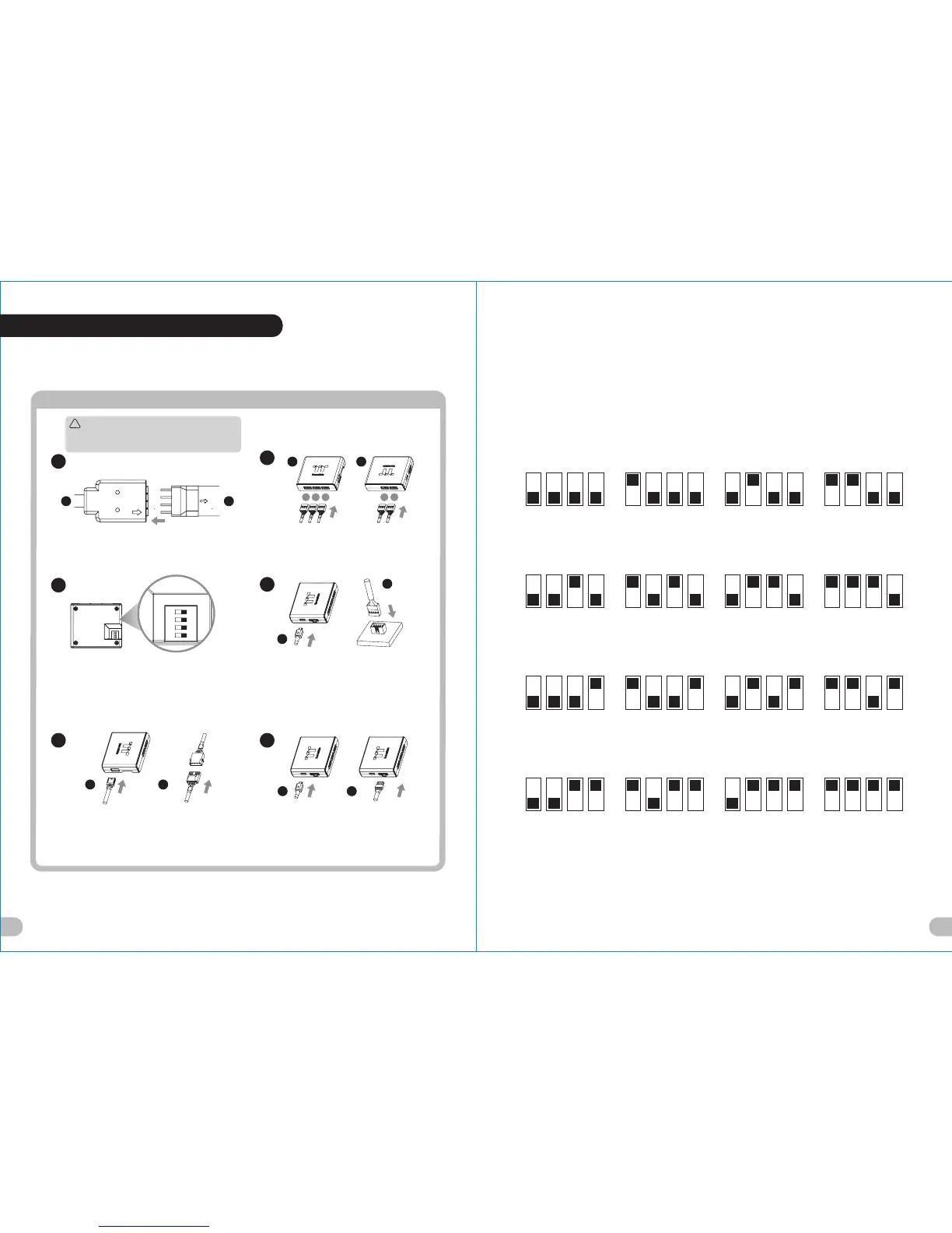
Connect the LED strip and LED cable.
Connect the cables onto the controller.
Set the DIP switch on the back side of the
controller to assign the number of the controller.
4
Connect the controller cable onto the
mainboard (USB 2.0 9 pin) and controller.
B
123 45
F
Please power off the PC and check the Positive ends on the
connection before connecting the LED strip to LED cable .
Connecting the wrong end can damage the LED strip.
1
3
G
!
Caution
NO.1
ON
1 2 3 4
NO.3
ON
1 2 3 4
NO.2
ON
1 2 3 4
NO.4
ON
1 2 3 4
NO.9
ON
1 2 3 4
NO.11
ON
1 2 3 4
NO.10
ON
1 2 3 4
NO.12
ON
1 2 3 4
NO.5
ON
1 2 3 4
NO.7
ON
1 2 3 4
NO.6
ON
1 2 3 4
NO.8
ON
1 2 3 4
NO.13
ON
1 2 3 4
NO.15
ON
1 2 3 4
NO.14
ON
1 2 3 4
NO.16
ON
1 2 3 4
65
(Another controller is optional)
Connect the power cable to the 4 pin
Molex connecter and controller.
E E
C C
Tt RGB Plus Installation
19 20