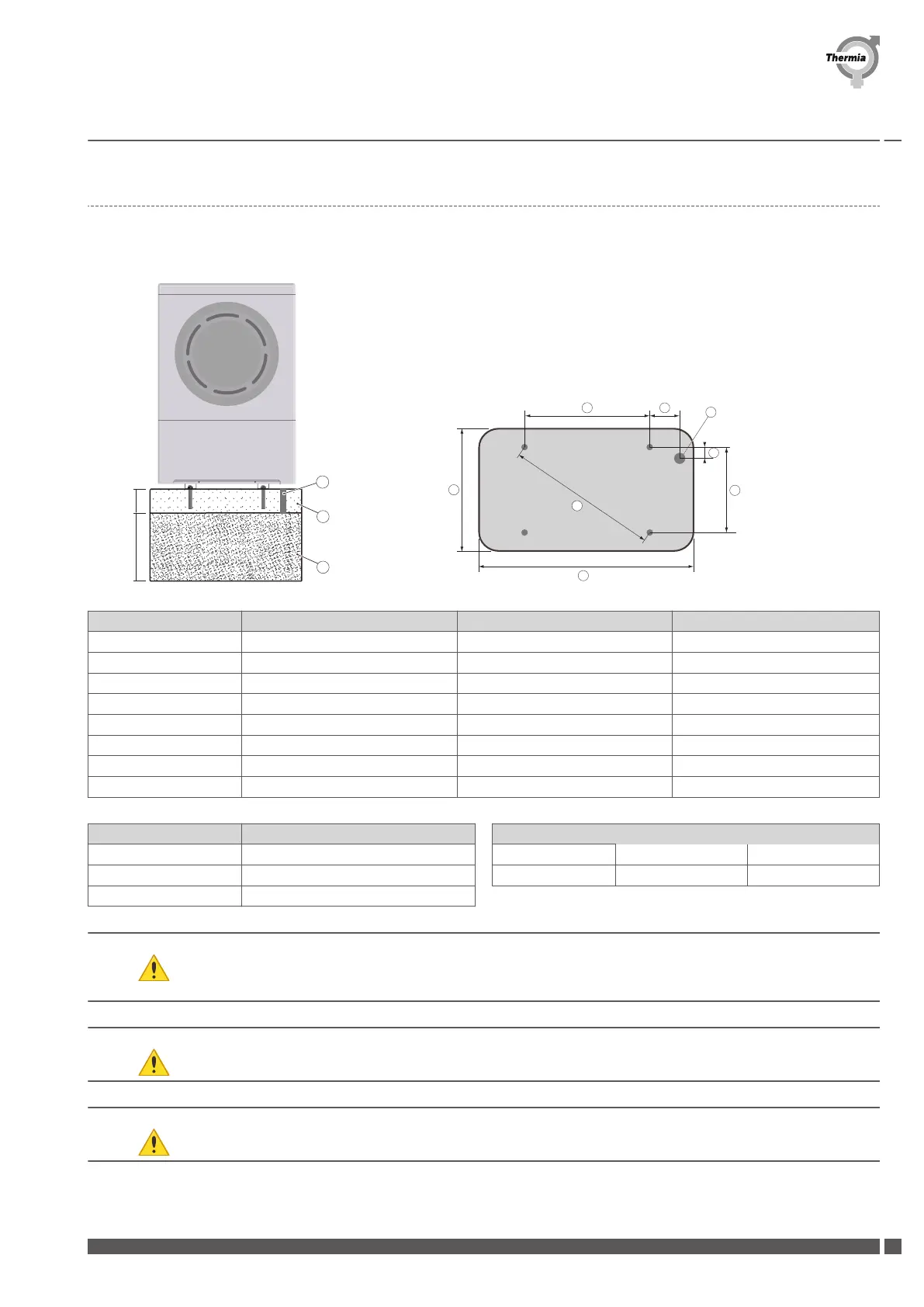
1.3.1 Heat pump foundation
1. The heat pump must be positioned outdoors on a stable base that can take the total weight of the heat pump, see Technical data.
2. Secure all four mounting points on a stable base, for example a cast foundation.
Measurements 6-9 kW 11-13 kW 16-18 kW
1 450 mm 470 mm 710 mm
2 424 mm 480 mm 480 mm
3 618 mm 672 mm 857 mm
4 130 mm 190 mm 145 mm
5 61 mm 65 mm 65 mm
6 ~1,000 mm ~1,200 mm ~1300 mm
7 ~650 mm ~720 mm ~720 mm
8 Ø 65 mm Ø 65 mm Ø 65 mm
Position Description
a Drainage hole
b Foundation
c Gravel
Bolt size
6-9 kW
11-13 kW 16-18 kW
M10 (4x) M12 (4x) M12 (4x)
Caution A driptray is installed with the purpose of gathering and draining away melt water during defrosting. Connect
a hose or pipe along with a heat trace cable between the outlet of the drip tray and a drain or a free draining
piece of ground. The heat cable must be connected to the terminal provided and is necessary to prevent ice
blockage.
Caution Check with a spirit level that the heat pump is installed horizontally.
Caution Incorrect positioning of the heat pump risks reduction of performance.
Planning guide Atec
Thermia Värmepumpar VIIFB102
5
 Loading...