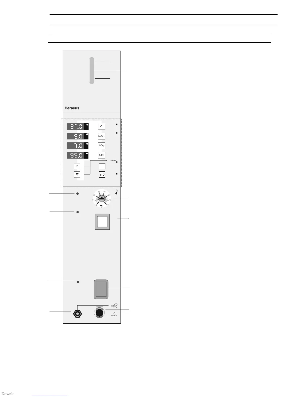
Switch panel
(A) "Control and display panel" (refer to Fig. 7)
(1) Indicator lamp "Fault, overtemp. protection"
(2) Indicator lamp "Disinfection mode"
(3) Indicator lamp "Master Switch"
(4) Vent/overflow "Water supply"
(5) Level gauge "Water supply"
(6) Setting knob "Temperature protection device"
(7) Press button "Disinfection mode"
(8) Master switch
(9) Quick-release coupling "Add/drain water"
Fig. 4: Switch panel
6. OPERATE
50 079 041 15/45
max
min
autozero
des
a q u a d e s t
&
&2
D
uto-start
contr ol
L
,
d e s
s t a r t