Thermo Scientific HyPerforma G3Pro Universal Bioreactor Controller User’s Guide | 18
Chapter 1 | G3Pro overview
The components listed are described below.
• Start/Reset—Pressed after system is powered on with the Main
Power Switch. It will allow the systems to enter the “ready to use”
status. Note: The Start/Reset button must also be pressed after an
emergency stop to restart the system.
• Emergency Stop (E-Stop)—Stops all activities of the G3Pro
controller, although sensor monitoring will continue. When the
button is pressed, it will remain depressed and show a red light, as
well as sounding an audible alarm. To release the E-Stop button,
turn it 1/4 turn clockwise and it will return to the original position,
silence the alarm, and shut o the red light.
• Pump Heads—Controlled by SmartPump motors with individual
microprocessors for maximum control and accuracy. The pump
heads are peristaltic variable-speed Watson-Marlow
™
stop on open
pump heads, the size determined by customer specifications (see
Tabl e 2.1).
• Pump jog—Used run the pump at a constant low speed for as
long as the button is depressed.
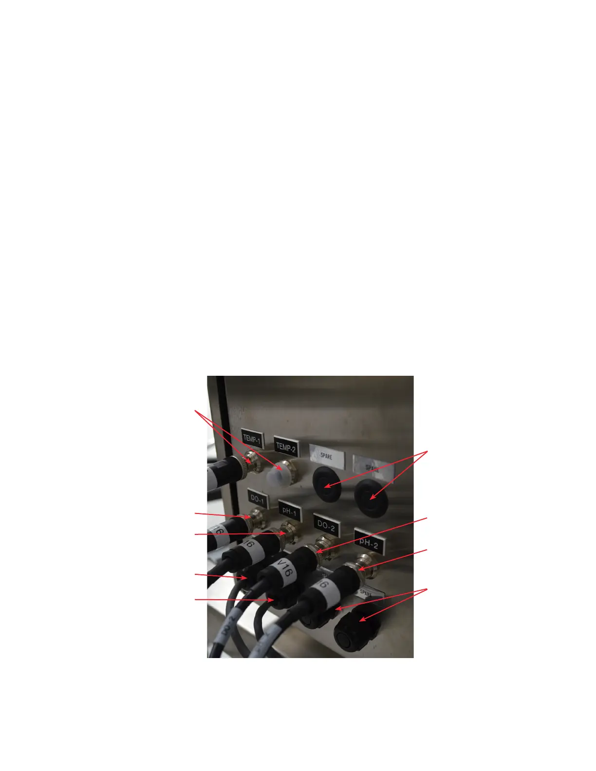
The lower half of the right side panel is shown below.
Figure 1.7. Lower half of the right side panel with
sensor connections.
Spares
DO-2 connector
Spares
pH-2 connector
DO-1 connector
pH-1 connector
DO-3 connector
pH-3 connector
Temp 1 and 2
connectors