4-1
KRF
4. Specifications
4-1
Basic specification
4.
Specifications
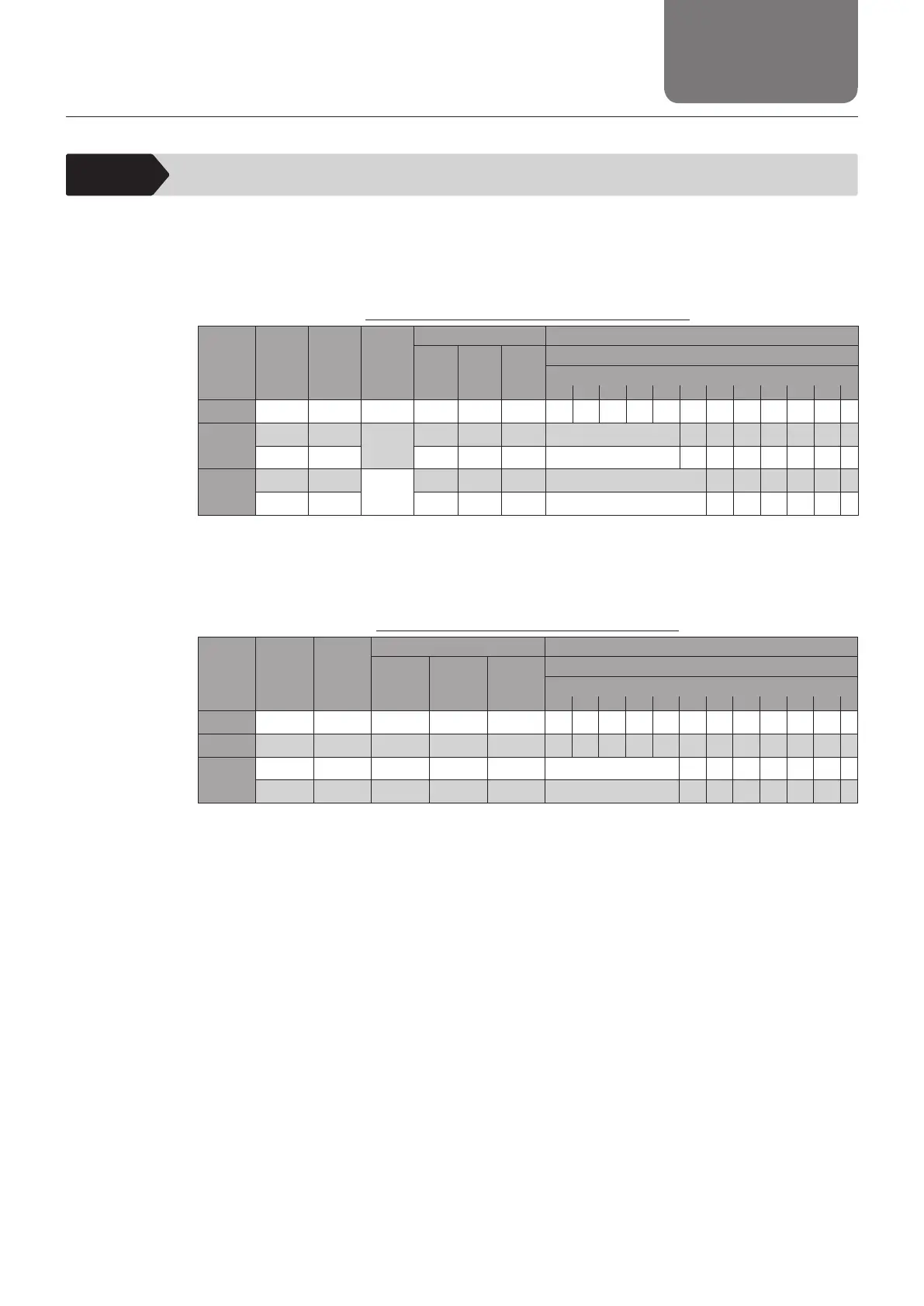
The basic specication of KRF is shown as follows. Do not exceed the following basic specication
when using the product. Otherwise, it may cause fault or damage, or may cause abnormal
operation that could lead to injury.
When using servo driver controller TLC/THC
Model
number
Ball screw
lead
[mm]
Stroke
[mm]
Motor
rated
output
[W]
Maximum load capacity
*2
[kg]
Maximum speed at each stroke
*3
[mm/s]
Horizontal
mount
Wall
mount
Vertical
mount
Stroke
to 300 350 400 450 500 550 600 650 700 750 800
KRF4 6 50 to 300 50 6 5.5 4 300
KRF5
6 50 to 550
50
19 14 6 300 250
10 50 to 550 15 12.5 3.5 500 430
KRF6
6 50 to 800
100
35 24 10 300 260 220 200 170 150
10 50 to 800 30 22 5 500 440 380 330 290 260
*1 This assumes a speed at the rated motor revolution (3,000min
-1
).
*2 The maximum load capacity assumes the capacity at the rated speed under 0.5 G for horizontal and wall mounts,
and 0.3 G for vertical mount.
*3 The maximum speed is the value restricted by the motor rotational speed (at 3000 min
-1
) or by the permissible
rotational speed of the ball screw.
When using stepper driver controller TSC
Model
number
Ball screw
lead
[mm]
Stroke
[mm]
Maximum load capacity
*1
[kg] Maximum speed at each stroke
*1
[mm/s]
Horizontal
mount
Wall
mount
Vertical
mount
Stroke
to 300 350 400 450 500 550 600 650 700 750 800
KRF3 6 50 to 300 3 3 1.5 300
KRF4 6 50 to 300 6.5 6 4 300
KRF5
6 50 to 550 20 14.5 7.5 300 250
10 50 to 550 10 10 6 500 430
*1 The maximum load capacity and the maximum speed vary with usage conditions. For details, see "Basic
specication" and "Speed and Load Capacity Relationship Diagram" for each model number.