9.
Appendix
9-2
KRF
9. Appendix
9-4
Static permissible load
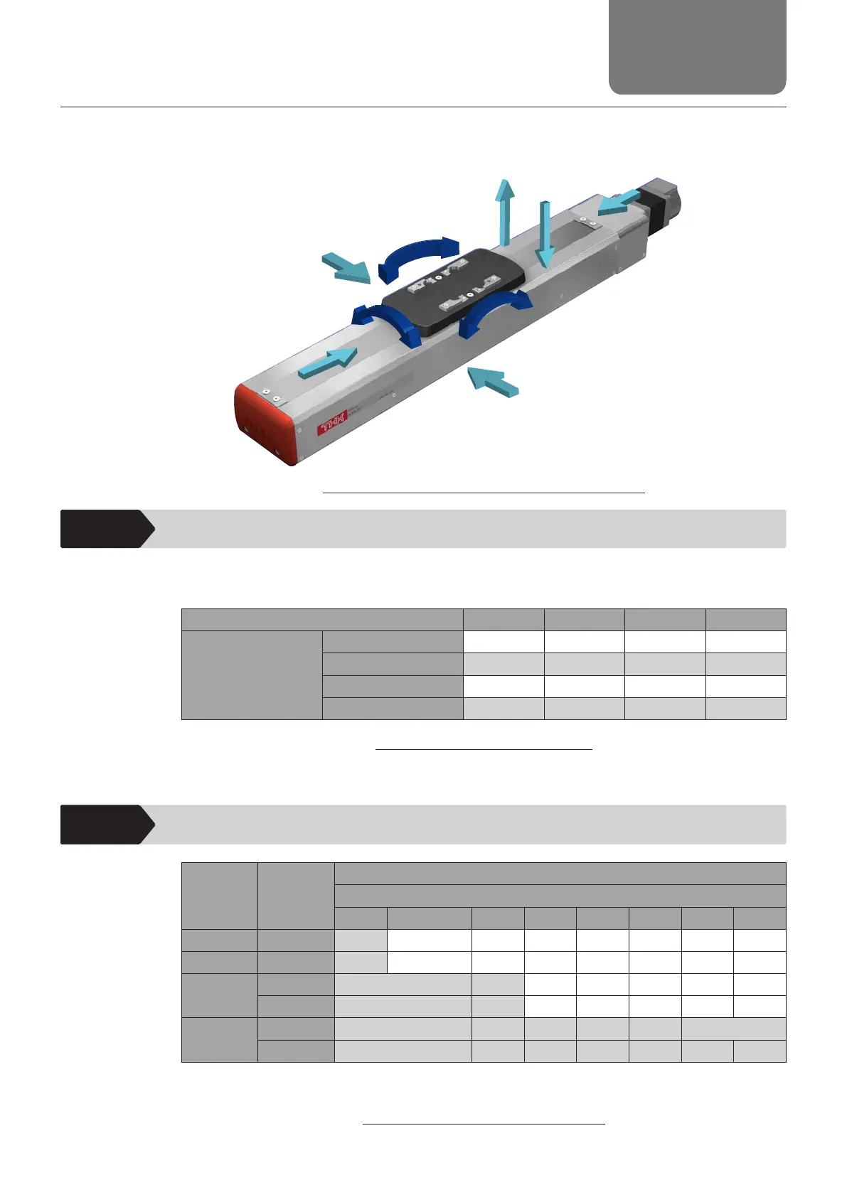
Static permissible load is shown in Table 11. For the direction of the load, see Fig. 6.
(The static permissible load is the value when a load is applied only to one direction. )
Model number KRF3 KRF4 KRF5 KRF6
Static permissible load
[N]
Axial direction 290 955 1465 2023
Radial direction 3450 6300 12150 20200
Reverse radial direction
3450 4048 6472 12380
Lateral direction 1095 1095 1899 3095
Table 11 Static permissible load
Note: The static permissible load is the maximum load permissible under the static condition.
9-5
Permissible rotational speed
Model
number
Lead [mm]
Permissible rotation speed at each stroke [min
-1
] *
Stroke
to 300 350 to 500 550 600 650 700 750 800
KRF3 6 3000 - - - - - - -
KRF4 6 3000 - - - - - - -
KRF5
6 3000 2500 - - - - -
10 3000 2400 - - - - -
KRF6
6 3000 2750 2500 2000 1750 1500
10 3000 2700 2400 2100 1800 1650 1500
*
The permissible rotational speed is the value restricted by the motor rotational speed (at 3,000 min
-1
)
,
or by the permissible rotational speed of the ball screw.
Table 12 Permissible rotation speed
Axial direction
Axial direction
Lateral direction
Lateral direction
Reverse radial
direction
Radial
direction
MB
MC
MA
MA: Pitching
M
B: Yawing
M
C: Rolling
Fig. 6 Imposed load ratio and moment direction