7-4
KRF
7.
Installation and Operation
7.
Installation and Operation
7.
Installation and Operation
7-4
Motor mounting method
We have an intermediate ange to mount various motors in KRF.
[Direct coupled specification]
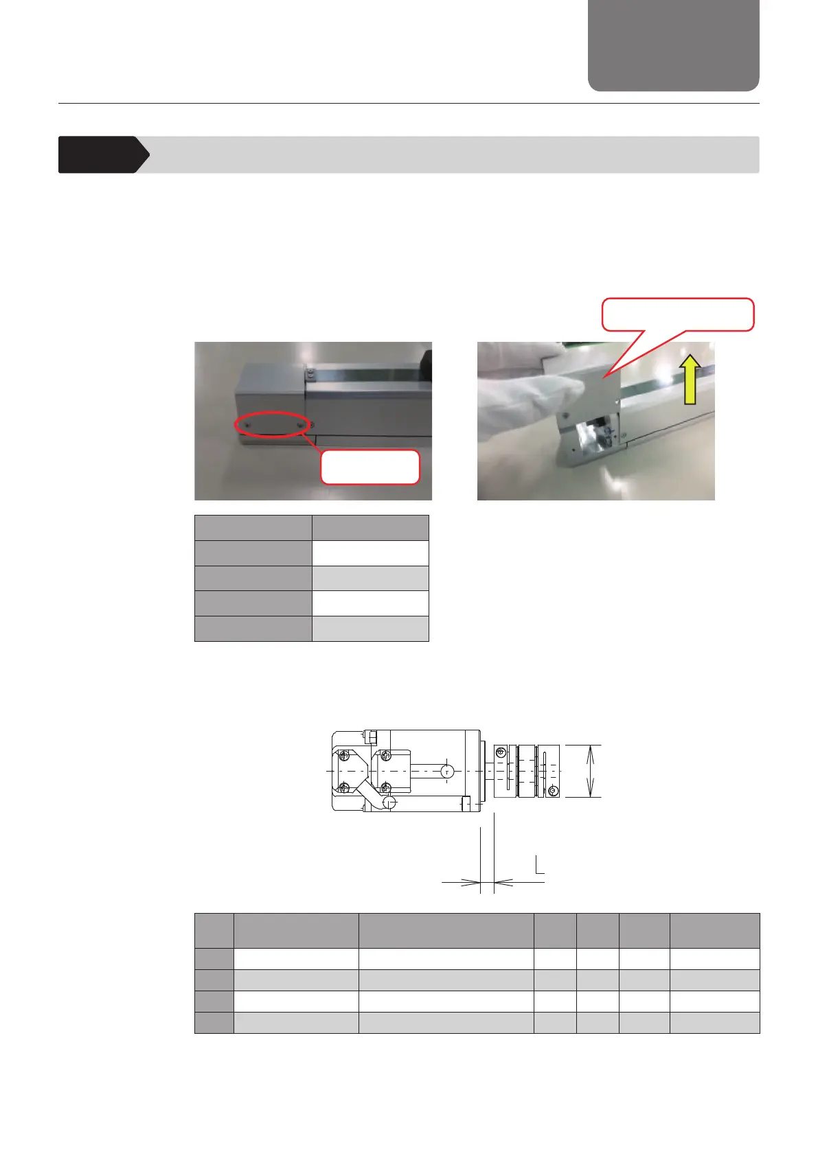
1. Remove the bolt and remove the housing A cover toward the direction of arrow.
Mounting bolt
Housing A cover
Model number Bolt size
KRF3 M2.6 × 4L
KRF4 M2.6 × 4L
KRF5 M3 × 5L
KRF6 M2.6 × 5L
Bolt type: Thin head (FH type) head screws
2. Tighten the coupling onto the motor shaft.
φ
D
Model
number
Motor models Coupling models
L dimensions
[mm]
φD
[mm]
Clamping
bolt
Tightening
torque [N·mm]
KRF3
SGMMV-A2A (Yaskawa Electric Corporation)
SFC-005DA2-3B x 5B (Miki Pulley Co., Ltd.)
8 16 M2 40 to 50
KRF4
TS4602 (Tamagawa Seiki Co., Ltd.)
SFC-010DA2-4B-8B (Miki Pulley Co., Ltd.)
13 19 M2.5 100 to 110
KRF5
TS4602 (Tamagawa Seiki Co., Ltd.)
SFC-010DA2-5B-8B-T013 (Miki Pulley Co., Ltd.)
15.2 19 M2.5 100 to 110
KRF6
TS4603 (Tamagawa Seiki Co., Ltd.)
SFC-020DA2-6B-8B (Miki Pulley Co., Ltd.)
6.7 26 M2.5 100 to 110
* For selection, handling and mou
nting of
a coupling, see the respective catalog issued by the
coupling manufacturer.
* Check necessary data such as permissible torque, eccentricity, deection angle and tightening
torque of the assembly bolt.