8
ZIP 22
5
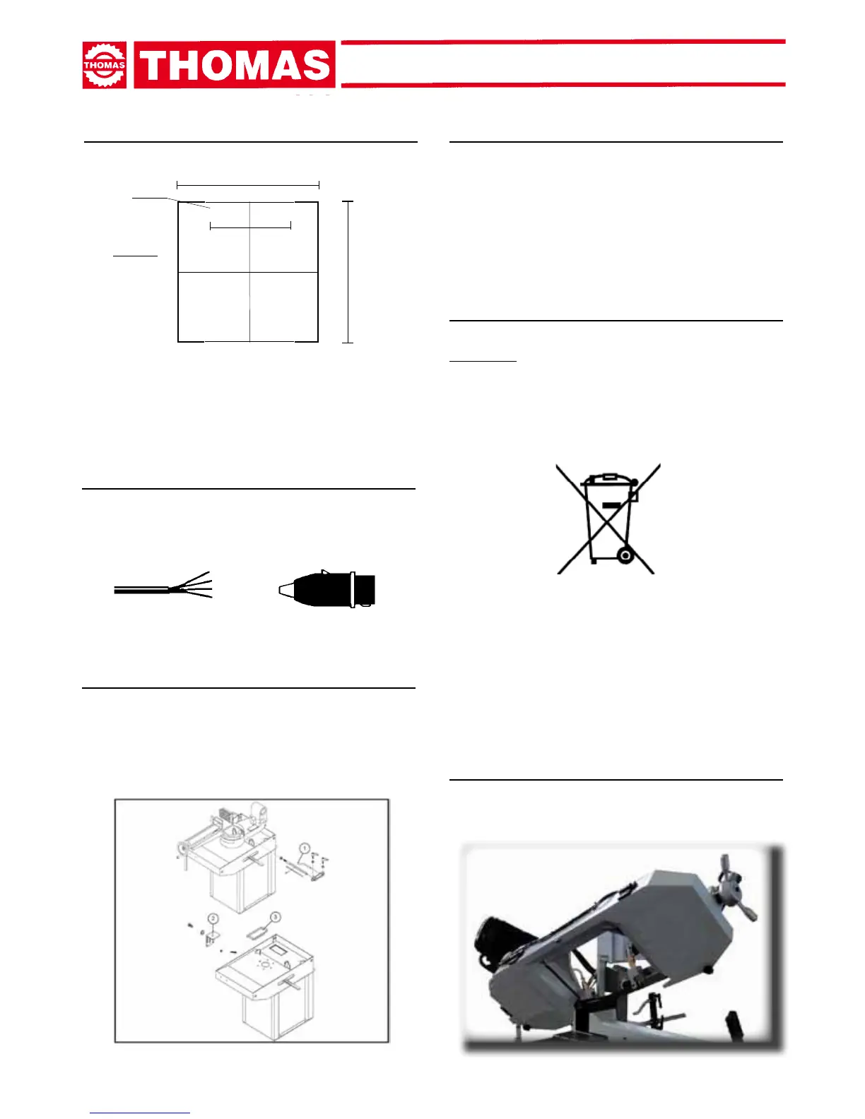
R = L1
S = L2
T = L3
PE = GND
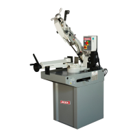
600mm
385mm
740mm
ø 10,5mm
OuterProle
4.4 - Anchoring the machine
- Positionthe machineona rmcementoor,maintaining,at
therear,aminimumdistanceof800mmfromthewall;anchor
it to the ground as shown in the diagram, using screws and
expansion plugs or tie rods sunk in cement, ensuring that it is
sitting level.
4.5 - Instructions for electrical connection
- The machine is not provided with an electric plug, so the cus-
tomermusttasuitableoneforhisownworkingconditions:
1 - WIRING DIAGRAM FOR 4-WIRE SYSTEM FOR THREE-
PHASE MACHINE - SOCKET FOR A 16A PLUG
4.6 - Instructions for assembly of the loose parts
and accessories
See following picture
1) Mount Bar-Stop n.1.
2) Material-Support n.2 should be set according to working table
levelandxedtotheposition.
3) Splash-Guard n.3 should be set in place to avoid coolant liquid
droppingdowntotheoor.
4.7 - Disactivating the machine
- If the sawing machine is to be out of use for a long period, it is
advisable to proceed as follows:
1) detach the plug from the electric supply panel
2) loosen blade
3) release the arch return spring
4) empty the coolant tank
5) carefully clean and grease the machine
6) if necessary, cover the machine.
4.8 - Dismantling
(because of deterioration and/or obsolescence)
General rules
ATTENTION: This symbol indicates that this product shall not be
treated as household waste. Instead it should be handed over
to the applicable collection point for the recycling of electrical
equipment. For more detailed information about recycling of this
product,pleasecontactyourlocalCivicOfce,yourhousehold
waste disposal service or the shop where you purchased the
product.
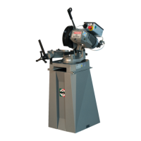
MACHINE FUNCTIONAL
PARTS
5.1 - Operating head or sawframe
- Machine part consisting of the members that transfer the motion
(gearmotor,ywheels),andtension/guide(blade-guides,blade
tension slide) and sawframe dowfeed control.