11
ZIP 22
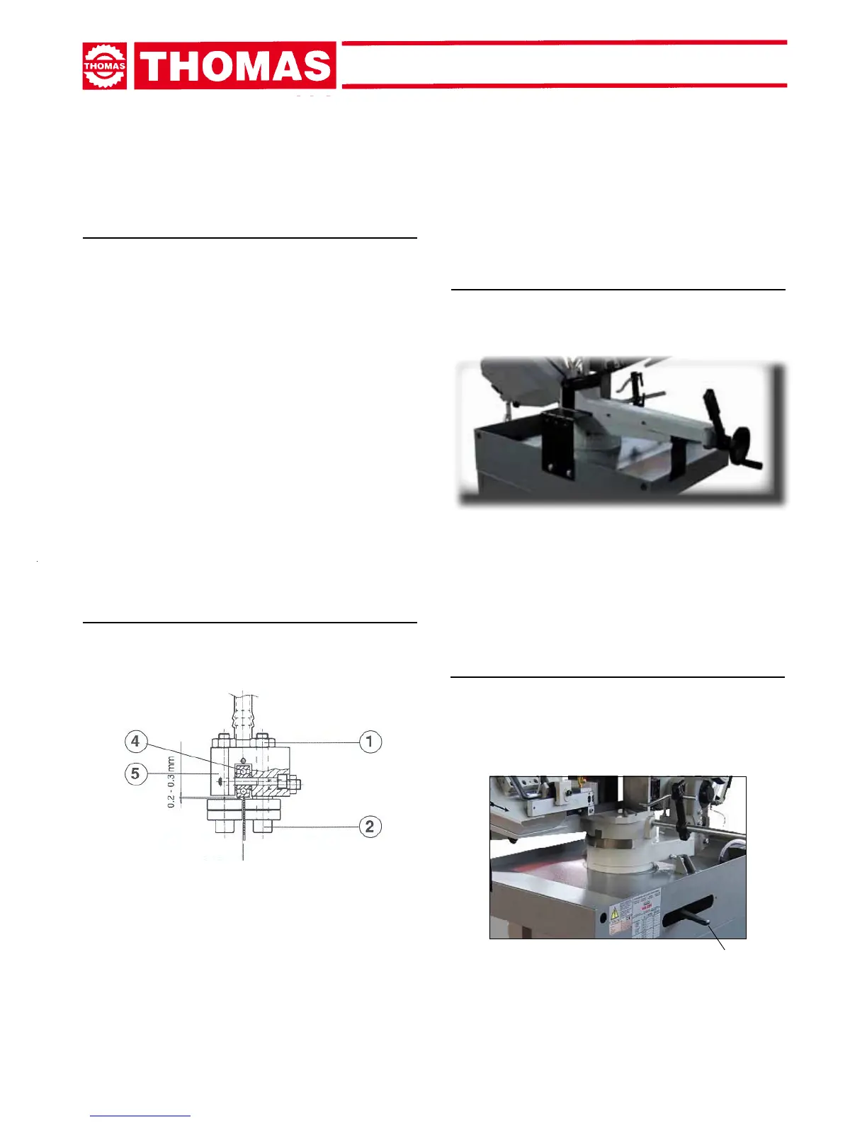
7.2 - Blade guide blocks
The blade is guided by means of adjustable rollers set in place
during inspection as per the thickness of the blade with minimum
playasshowninthegure.
In case the blade needs to be replaced, make sure to always
install 0.9 mm thick blades for which the blade guide rollers have
been adjusted. In the case of toothed blades with different thick-
nesses adjustment should be carried out as follows:
- Loosen the nuts ( 1 ) and rotate the pin ( 2 ) widening the pas-
sage between the rollers.
- Mount the new blade, place the rollers and rotate the pin ( 2 ) leaving
0,04mm clear to allow the blade sliding smoothely. Secure the Nut ( 1 ).
- Make sure that 0,2-0,3mm clear between the blade back and
theroller(4);Justincase,loosenthescrewsthatfastensthe
heads(5)andcarryoutnaladjustment.
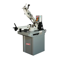
7.3 - Vice
- Thedevicedoesnotrequireanyparticularadjustment;incase
of excess play of the sliding guide, tighten slide screw more.
- Place material to be cut in the vice. Close jaws against piece,
keeping a distance of approx. 3 - 4 mm then clamp with lever.
REGULATING
THE MACHINE
7.1 - Blade tension assembly
-Turn clockwise the handwheel to put the blade under tension ac-
cording to the scale ( 10 ) showing 20, 30 and 35.000 psi (pounds
per square inch). Bi-metal M42 blades need to be tensioned to
30-35.000 psi, whilst for Carbon blades the tension should be
20.000 psi. At the end of each working day, it is reccomended
to loose the blade tension to a minimum. This will preserve the
exibilityofthebladeandguaranteelongerdurability.
7
6
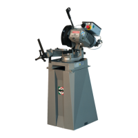
7.5 - Cutting angle adjustment
- Unlock lever (6) and rotate the saw frame arm until you
reach mechanical stop and check if the index corres-
pondsto60°;ifnotoperateonthesetscrewstomake
measures meet.