Thomson
Thomson Electrak
®
LL Actuator - Installation Manual - 2020-1110
Installation
4.5 Electrical installation
4.5.1 General notes
• Make sure the leads/cables leading to the motor can handle the maximum motor current.
• An emergency stop is recommended to reduce the chance of a crushing hazard.
• Never work on the actuator or the wiring with the power switched on!
4.5.2 Fuse size
Protect the actuator and the wiring by using a slow blow fuse between the actuator and the power source.
4.5.3 Electrical connections
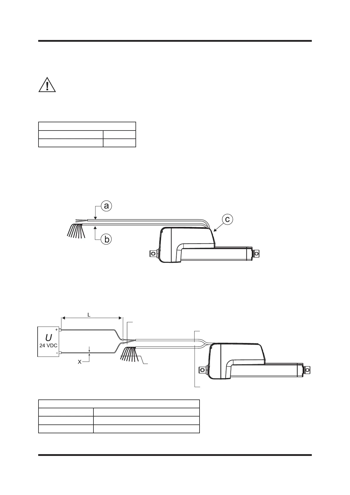
The actuator is always supplied with a power cable (a). Depending on which control option was selected, it
can also have a signal cable (b). The cable(s) have ying leads in one end for customer connections. In the
other end the cable(s) are integrated in to the cable connector cover plate (c) (section 4.4.4). The plug in
connector allows replacing the actuator without disconnecting the ying leads.
4.5.4 Lead cross sections
To avoid malfunction due to voltage drop the cross section of the leads between the actuator power
cable leads and the power source must be of sucient size. For longer cables than stated in the table,
calculations based on the supply voltage, the current draw, the length of the cables and the ambient
temperature must be done.
Power Lead Cross Sections
Length of cable (L) Min. allowed cross section (X)
0 - 4 m 1.5 mm
2
[AWG 16]
4 - 10 m 2.5 mm
2
[AWG 14]
Recommended Fuse Size
Actuator supply voltage Fuse size
24 Vdc 20 A
1.5 mm
2
[AWG 16]
Power cable
Signal cable
X
0.5 mm
2
[AWG 20]