Do you have a question about the THOMSON MEC 320 - GENSET CONTROLLER and is the answer not in the manual?
Outlines the general purpose of the MEC 320 reference handbook for users.
Identifies the primary audience and other potential readers for this operating manual.
Details the chapter breakdown and overall organization of the document for easy navigation.
Defines Thomson Technology's stance on installation, operation, and warranty voiding.
Advises on necessary precautions against static discharges during installation.
Highlights dangers of working with live equipment and the need for authorized personnel.
Explains the symbols and formatting used for notes and warnings in the manual.
Introduces the MEC 320 as part of the Thomson Technology product family.
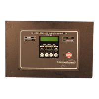
Describes the MEC 320 as a microprocessor-based control unit for genset protection.
Warns about potential hazards when remotely controlling the genset via PC software.
Lists operational modes, engine control, protections, display features, and M-logic.
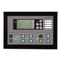
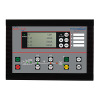
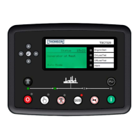
Describes the display's layout, lines, character count, and overall button functions.
Details the functionality of each push-button on the display unit for navigation and control.
Describes the menu system for viewing operational status and measurements.
Details the menu system for unit configuration, with password protection for settings.
Explains the initial window displayed upon power-up and how to access other menus.
Describes automatic operation where the unit initiates sequences without operator intervention.
Explains manual initiation of sequences via buttons, commands, or inputs for nominal operation.
Details how the test sequence is initiated and performed on the genset.
Covers manual control using inputs and buttons, starting without subsequent regulation.
Defines maximum paralleling time between generator and mains supply, applicable in specific modes.
Details the use of VDO input 104 for measuring lubricating oil pressure and its sensor types.
Displays alarm timers and remaining time, showing when set points are exceeded.
Shows the current status of the digital inputs connected to the controller.
Displays the current status of the digital outputs, such as horn and relay states.
Presents miscellaneous messages and information relevant to the unit's operation.
Guides users on locating parameter descriptions in Chapter 8 using the overview list.
Explains the possible adjustments and fields within the parameter tables for clarity.
Configures the function and delay for relays 9, 10, 11, 12, and 13.
Configures transistor outputs on terminals 20 and 21 for constant or pulse signals.
Configures nominal settings, transformer details, and engine type for system operation.
Configures low and high voltage alarms for the auxiliary power supply.
Configures the timer for the alarm horn relay activation.
Allows selection of the display language, with English as default.
Configures parameters for the starter, including prepare time, ON/OFF times, and number of teeth.
Manages the number of start attempts and associated relay outputs during a start sequence.
Defines cooldown time, extended stop, and coil type for stopping the gen-set.
Configures timers and relay outputs for frequency/voltage OK and failure conditions.
Configures derating parameters based on input signals, start points, slope, and limit.
Sets minimum and maximum power values for day, night, and transducer settings.
Defines the start and stop hours/minutes for the daytime period.
Configures parameters for starting, stopping, and testing the generator.
Sets a fixed power output level for the generator.
Accesses software version information and configures the RS232 service port.
Manages user, service, and master passwords for parameter access restriction.
Accesses service functions like alarm status, digital input/output status, and miscellaneous information.
Selects the system configuration for single, split, or three-phase operation.
| Brand | THOMSON |
|---|---|
| Model | MEC 320 - GENSET CONTROLLER |
| Category | Controller |
| Language | English |




 Loading...