Do you have a question about the THOMSON TSC 80E - V2.2 and is the answer not in the manual?
Important notes and precautions for installers regarding voltage, phasing, and testing.
Instructions for connecting the "High" leg in 3-phase 4-wire delta systems to ensure proper control power.
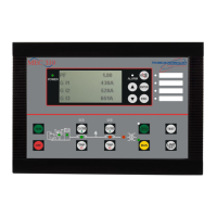
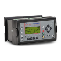
Comprehensive list of features and capabilities of the TSC 80e controller.
Description of the different types of output circuits provided by the TSC 80e.
Step-by-step description of the automatic transfer switch operation during power failures and restorations.
Detailed explanation of the standard automatic transfer switch operation during utility power events.
Describes how the controller handles abnormal conditions like generator failure and transfer failures.
How transfer failures are detected when the switch is not actively transferring.
How transfer failures are detected during the transfer process itself.
Procedures for various test modes to simulate conditions and verify functionality.
How to simulate a utility power failure to test the automatic transfer to generator supply.
Procedure to reset a Transfer Fail condition and how the system behaves afterward.
Information on the password system for accessing and protecting programmable parameters.
Step-by-step procedure for entering passwords to access programming menus.
General procedure for navigating and changing program values after entering the correct password.
A step-by-step guide for quickly changing the system voltage programming.
A step-by-step guide for programming the functions of the programmable output relays.
Configuration settings for system voltage, frequency, phases, and other parameters.
Sets the system voltage for the TSC 80e controller from a list of twelve options.
How to calculate and set under voltage setpoints for non-standard system voltages.
Procedure for field calibrating voltage-sensing circuitry for utility and generator.
Steps to zero calibrate the generator voltage sensing inputs.
Steps to zero calibrate the utility voltage sensing inputs.
Steps to span calibrate the generator voltage sensing inputs using an external voltmeter.
Steps to span calibrate the utility voltage sensing inputs using an external voltmeter.
Details for programming utility voltage pickup and dropout setpoints with adjustable hysteresis.
Setting the utility under voltage setpoint at which the sensor drops out.
Setting the utility under voltage setpoint at which the sensor picks up.
Programming generator voltage and frequency setpoints, including pickup and dropout.
Setting the generator under voltage setpoint at which the sensor drops out.
Setting the generator under voltage setpoint at which the sensor picks up.
Setting the generator under frequency setpoint at which the sensor drops out.
Setting the generator under frequency setpoint at which the sensor picks up.
Specific control and timing delay logic for utility and generator operation.
Functions that can be assigned to the programmable output relays.
Table indicating all programmable settings and their factory default values.
| Brand | THOMSON |
|---|---|
| Model | TSC 80E - V2.2 |
| Category | Controller |
| Language | English |



 Loading...