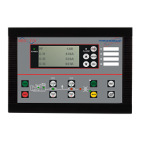
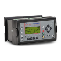
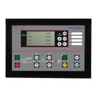
TSC 80e TRANSFER SWITCH CONTROLLER
PM091 Rev 1 09/02/27 Thomson Technology
8
2.2.1. TERMINAL BLOCKS
Terminal blocks are located on the PCB as follows:
TB1 High voltage sensing terminal block (120-600VAC).
WARNING
Voltage sensing circuits are capable of lethal voltages while
energized. Standard safety procedures should be followed and
be performed by qualified personnel only. Failure to do so may
cause personnel injury and/or death.
TB2-TB6 Transfer control terminal block for 120VAC control power and input/output
circuits.
TB7 Low voltage control inputs (5VDC internally powered, switched to terminal
38).
2.2.2. DIAGNOSTIC LED’S
The TSC 80e controller provides diagnostic LED lights, which are mounted on the
printed circuit board as per FIGURE 2. Their functions are described as follows:
SYS OK LED flashes on and off at irregular intervals, which indicates
the microprocessor is functioning normally.
XFER TO UTILITY LED illuminates whenever the TSC 80e is initiating a signal
to transfer to the Utility supply. (UP transfer contact as noted
on the electrical schematic is closed)
XFER TO GEN LED illuminates whenever the TSC 80e is initiating a signal
to transfer to the Generator supply. (GP transfer contact as
noted on the electrical schematic is closed)
ENG STOP LED illuminates whenever the TSC 80e is initiating an
ENGINE STOP (remote start contact is open).
PROG 1 LED illuminates whenever the Programmable output Relay
#1 is turned on (relay on the circuit board is energized).
PROG 2 LED illuminates whenever the Programmable output Relay
#2 is turned on (relay on the circuit board is energized).
PROG 3 LED illuminates whenever the Programmable output Relay
#3 is turned on (relay on the circuit board is energized).
 Loading...
