Do you have a question about the THOMSON MEC 310#GENSET CONTROLLER and is the answer not in the manual?
General information about the handbook's purpose and scope.
Identifies the primary audience for the handbook.
Outlines the chapter structure and overall document organization.
Highlights safety considerations during installation and operation.
Precautions for handling electronic components to prevent static damage.
Notes that factory settings may need adjustment for specific engines.
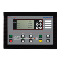
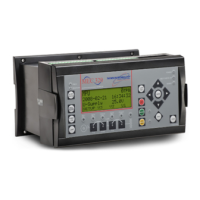
Introduces the MEC 310 as a cost-effective control unit for generators.
Lists key engine control and monitoring features of the unit.
Details available optional features like AMF and communication modules.
Provides instructions for flush mounting the unit in enclosures.
Details the rear view of the unit and its terminal connections.
Illustrates various wiring diagrams for communication and inputs.
Instructions for Modbus RTU and CANbus communication setup.
Lists electrical and environmental specifications of the unit.
Explains the function of each button on the front panel.
Describes the status indications provided by LEDs.
Explains how readings and alarms are shown on the display.
How the unit detects, displays, and acknowledges alarms.
Describes definite time delay functions with set points.
Lists configurable relay outputs and their factory settings.
Defines categories of alarms and their actions.
How parameters are organized into groups.
Detailed settings for engine protection alarms.
Configuration of service timer 1.
Configuration of idle mode operation.
Settings for the emergency stop function.
| Brand | THOMSON |
|---|---|
| Model | MEC 310#GENSET CONTROLLER |
| Category | Controller |
| Language | English |
