EasyManuals Logo

THOMSON MEC 310#GENSET CONTROLLER User Manual

THOMSON MEC 310#GENSET CONTROLLER
119 pages
To Next Page IconTo Next Page
To Previous Page IconTo Previous Page
Page #66 background imageLoading...
Page #66 background image
MEC 310 GENSET CONTROLLER
PM075 REV 2 09/08/20 Page 62 THOMSON TECHNOLOGY
RPM inputs
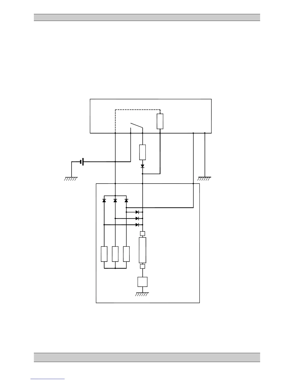
Charger alternator connections
This schematic diagram shows the basic way the charger alternator and the MEC 310 can
cooperate.
Only one running feedback is needed, but for optimal safety and function both the RPM (Tacho)
input and the digital running feedback (D+) can be used as in the example below.
Rex: Excitation resistor: 12V systems: 47 3 W
24V systems: 100 6 W
MEC 310
RPM
Starte
r
(Crank)
Running
Feedback
Input
9
23
22
12
18
17
Rex
1N4007
+
-
Battery
B+
D+
W
Brush
Brush
Excitation
Controller
Coil (rotor)
Exciter
Charge
Alternator
U
V
W
Stator

Table of Contents

Questions and Answers:

Question and Answer IconNeed help?

Do you have a question about the THOMSON MEC 310#GENSET CONTROLLER and is the answer not in the manual?

THOMSON MEC 310#GENSET CONTROLLER Specifications

General IconGeneral
BrandTHOMSON
ModelMEC 310#GENSET CONTROLLER
CategoryController
LanguageEnglish

Related product manuals