MEC 310 GENSET CONTROLLER
PM075 REV 2 09/08/20 Page 7 THOMSON TECHNOLOGY
4. Installation instructions
This chapter includes the information needed to perform correct installation of the unit, e.g.
mounting instructions, terminals, wiring, inputs etc.
Mounting
The unit is designed for flush mounting by means of 4 fixing clamps (IP52), which are included at
delivery. To have the IP65 (12 fixing clamps) the unit must be ordered with option L. The two fixing
clamps on each side are mounted on the top and bottom of the MEC 310 box.
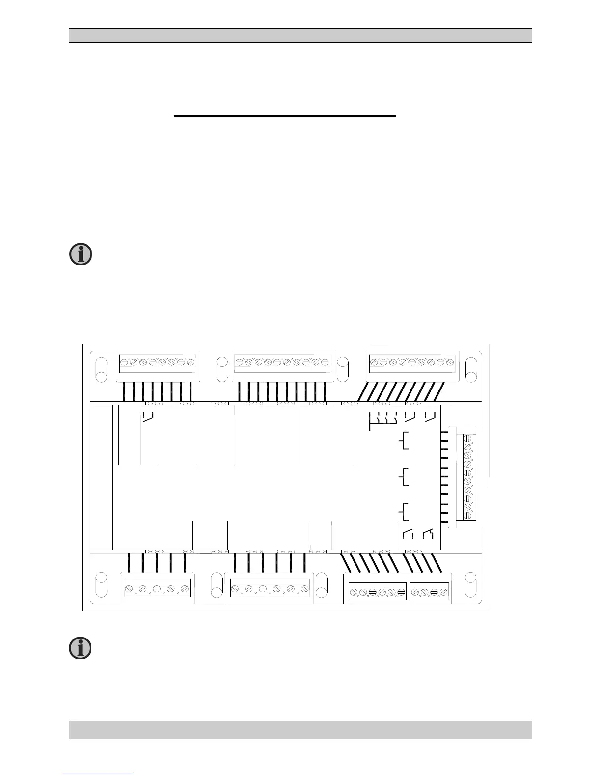
Terminals
Unit rear view
For Use on a Flat Surface of a Type 1 Enclosure.
The RJ11 connector for the PC connection i
nterface (SSP) is placed on the side
of the unit.
1 2 3 4 5 6 7 8
9 10 11 12 13 14 15 16 17 18
19 20 21 22 23 24 25 26 27
28 29 30 31 32
33 34 35 36 37 38
L1 N L2 NA L3
L1 N NA L2 NA L3
Mains Voltage
Generator Voltage
+ 0 1 2 3
com
DC
Power
supply
Status
Multi functional
1 2 3 4 5 6
com
Tacho
com
Tacho w/capacitor
com
Binary inputs
E-Stop
45 46
39 40 41 42 43 44
L1
Generator Current
L2
L3
49
50
51
52
53
54
55
56
57
58
59
Can L
com
Can H
Can 1 J1939
Option J
47 48
TX
com
RX
modbus
RS485
(option M)
EAP
Can 2
Can H
com
Can L