Do you have a question about the THOMSON TSC 800 - V2.2 and is the answer not in the manual?
Historical summary of changes made to the TSC 800 product since its original release.
Overview of the TSC 800 controller's microprocessor-based design and features.
General notes regarding site installations and adherence to electrical codes.
Key considerations and warnings for installers regarding voltage matching and configuration.
Details on acceptable AC voltage sensing inputs and system requirements.
Information on the required AC control power input voltage and consumption.
Description of the different types of output circuits provided by the TSC 800.
Guidelines for connecting to 3-phase 4-wire delta systems with high leg.
Minimum requirements for external panel control wiring, including wire sizes.
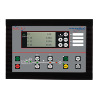
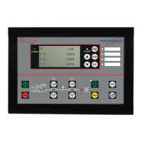
Description of the Lexan faceplate and its interactive elements.
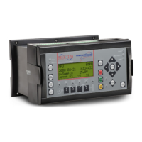
Identification of user interface items on the printed circuit board.
Procedure for selecting the correct power supply input voltage using jumper plugs.
Details on the three terminal blocks and their respective functions.
Explanation of the functions of the four diagnostic LEDs on the PCB.
Displays current system time and week number for automatic exercise scheduling.
Allows manual selection of operating modes like Auto, Offload, and Onload Test.
Access to programmable functions like time delays and setpoints via password.
Provides real-time status information for utility and generator supplies.
Detailed description of the automatic transfer switch operation sequences.
Step-by-step process for open transition transfer during utility failure.
Process for closed transition transfer, including synchronization logic.
Explains test modes like utility power fail simulation and closed transition tests.
Procedure for manually simulating a utility power failure for testing.
Procedure to reset a Transfer Fail condition and re-transfer to the source.
Initiating a re-transfer to the utility supply manually after a failure.
Handling phase balance alarms and re-transfer sequences.
Explanation of the three levels of security passwords for parameter access.
Details on accessing parameters in read-only mode.
Details on accessing parameters for viewing and modifying.
Access to all parameters and security password level modification.
Programming the automatic exercise timer for generator tests.
Selecting the type of automatic test mode (Auto, Off Load, On Load).
Configuring system parameters like voltage, frequency, and phases.
Setting the nominal system voltage for the controller.
Configuring phase balance protection thresholds and delays.
Configuration of utility and generator voltage sensing parameters.
Setting the utility under voltage threshold for sensor pickup.
Setting the generator under voltage threshold for sensor pickup.
Programming generator control logic parameters like start and delay timers.
Setting the delay time before initiating a generator start signal.
Configuring the transfer fail detection and response modes.
Guidelines for calibrating voltage sensors for utility, generator, and load.
Procedure for calibrating utility supply voltage sensors (Zero and Span).
Procedure for calibrating generator supply voltage sensors (Zero and Span).
| Brand | THOMSON |
|---|---|
| Model | TSC 800 - V2.2 |
| Category | Controller |
| Language | English |



 Loading...