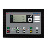
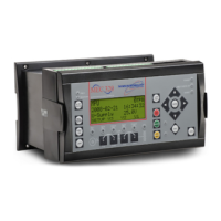
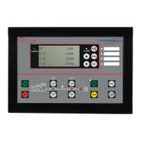
TSC 800 TRANSFER SWITCH CONTROLLER
PM 049 REV 10 08/09/25 Thomson Technology
30
signal will be removed (logic contact(s) opening) and the transfer to generator supply
signal (logic contact(s) closure) will be given to the transfer switch Power Switching
Devices. The load will then transfer from the utility supply (i.e. opening the utility
power switching device) to the generator supply (closing the generator power switching
device) to complete a break-before-make open transition transfer sequence.
The generator will continue to supply the load until the utility supply has returned and
the retransfer sequence is completed as follows: When the utility supply voltage is
restored to above the present values (70 - 99% of rated adjustable) on all phases, a
re-transfer sequence will be initiated once the Utility Return timer expires. The utility
will close its power-switching device when it is in synchronism with the generator
supply via external logic device. If the transfer switch is supplied with a “Momentary”
Closed Transition transfer control option, the generator power switching device will
immediately trip open approximately 50-100 milliseconds after the utility power
switching device closes to complete the “make-before-break” re-transfer sequence. If
the transfer switch is supplied with a “Soft-Load” Closed Transition transfer control
option, the generator power switching device will remain closed for approximately 5-10
seconds to allow a soft-load power transfer sequence to be completed as controlled by
an external device. The generator power switching device will then trip open to
complete the “make-before-break” re-transfer sequence.
An engine cooldown timer circuit will be initiated once the load is transferred from the
generator supply and determined to have made position by ensuring the load bus is
energized and the utility position indication confirmed. Following expiry of the
cooldown delay period (0.0 – 50.0 min. adjustable) the engine start signal will be
removed (remote start contact opened) to initiate stopping of the generator set.
6.1.3. TEST MODE SEQUENCE OF OPERATION
6.1.3.1. TEST CONDITION (OPEN TRANSITION TRANSFER)
When an operator selects a test mode it shall signal a simulated utility power fail signal
to the transfer switch controller. The transfer switch shall operate as per a normal
utility power fail condition. The neutral delay circuit logic will be active during transfer
to and from the generator supply (i.e. when both sources of power are available). (For
definitions and added features refer to Section 7.5.12.)

 Loading...


