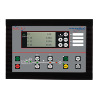
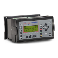
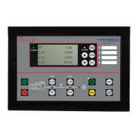
TSC 800 TRANSFER SWITCH CONTROLLER
PM 049 REV 10 08/09/25 Thomson Technology
3
The following installation guidelines are provided for general information only pertaining to
typical site installations. For specific site installation information, consult Thomson
Technology as required. NOTE: Factory installations of THOMSON TECHNOLOGY supplied
transfer switches that have been tested and proven may deviate from these
recommendations.
2.2. NOTES TO INSTALLER
If the transfer switch has programmable/multi-tap system voltage capability (refer to electrical
schematic), confirm the transfer switch has been configured for the system voltage.
WARNING
Failure to confirm and match transfer
switch voltage with the system voltage
could cause serious equipment damage.
If the transfer switch requires reconfiguring, the TSC 800 controller will also require
reprogramming.
CAUTION!!!
Qualified personnel must complete all installation and/or service work
performed only. Failure to do so may cause personal injury or death.
2.3. AC VOLTAGE SENSING INPUT
The TSC 800 can accept direct AC voltage sensing inputs on the generator and utility supplies
from 120-600VAC (nominal). NOTE: Direct input voltage sensing can only be used when the
system utilizes a 3 phase, 4 wire distribution system which has the neutral conductor solidly
grounded. For 3 phase, 3 wire systems (i.e. no neutral) or high voltage systems, potential
transformers must be used (this is also the case where only 1 of the 2 supplies are 3 ph 3 w).
Refer to FIGURES 1-4 for voltage sensing connections.
2.4. AC CONTROL POWER INPUT
The TSC 800 is factory supplied for either 115VAC or 230VAC (nominal) control power input
voltage. Independent AC control power is required from both utility and generator supplies.
AC control power is utilized for internal TSC 800 control circuits and external control device
loads. The TSC 800 requires approximately 12VA AC power for internal control circuits. The

 Loading...


