YOUR RECEIVER
P7
WARNING Indicates warning information.
NOTE Indicates any other additional important or helpful information.
MENU Represents a button on the remote control or the receiver.
(Bold characters)
Move to Represents a menu item within a screen.
(Italic characters)
1.4 Accessories
• 1x Quick Installation Guide
• 1x remote control unit
• 2x batteries (AAA type)
• 1x adapter 12 Volt DC, 2 Ampere
WARNING: The batteries should not be recharged, disassembled, electrically short-circuited, be mixed or used
with other types of batteries. If rechargeable accumulators instead of batteries are going to be used,
we recommend using (e.g. NiMH) types with low self-discharge to ensure long time operation of
remote control.
1.5 Usage of external USB devices
• It is recommended to use USB 2.0 storage devices. If your device is not compatible to USB 2.0 specifications,
recording, Timeshift and playback with your receiver might not work properly.
• If you are going to use external USB HDD (Hard Disk Drive) please consider that it might be the case that the
power specifications exceed the supported output of your receiver (5V/1A). If so, please connect your USB HDD
to an according external power adapter.
• THOMSON cannot guarantee compatibility with all types of USB storage devices.
• It is advised not to store important information on USB storage devices used with the receiver. Always
make backups of data on your USB storage device before using it with this receiver. THOMSON will not take
responsibility for any loss of information or circumstances caused by loss of information.
Please ensure that either the USB device is already formatted to FAT32, or format the USB device via your
receiver, refer to chapter 7.4.4 HDD Manager in the user manual available on our website www.thomsonstb.
net/downloads/manuals/THS813_UM_EN.pdf for details.
THOMSON cannot guarantee the playback of all files although extensions are listed, as it depends on file size,
codec, bit rate and resolution.
2.0 YOUR RECEIVER
2.1 DEFAULT PIN-CODE: 0000
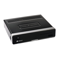
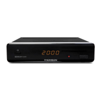
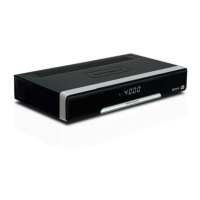
2.2 Front Panel
Fig.1
1. Standby/ON button Switches the receiver ON or into Standby
2. IR Sensor Receives the RCU commands
3. Indicator LED GREEN indicates that the receiver is currently ON, GREEN and RED alternating indicates
that the receiver is preparing to enter deep sleep, RED indicates that the receiver is
currently in deep sleep mode.
4. LED Display Displays channel number, time, videotext page or PVR modes
5. Smart card slot To insert your valid and activated Irdeto smart card for proper reception of your desired
channel bouquet. For the correct insertion of smart card please see the insertion
drawing (fig 1).
6. USB To connect your USB storage device