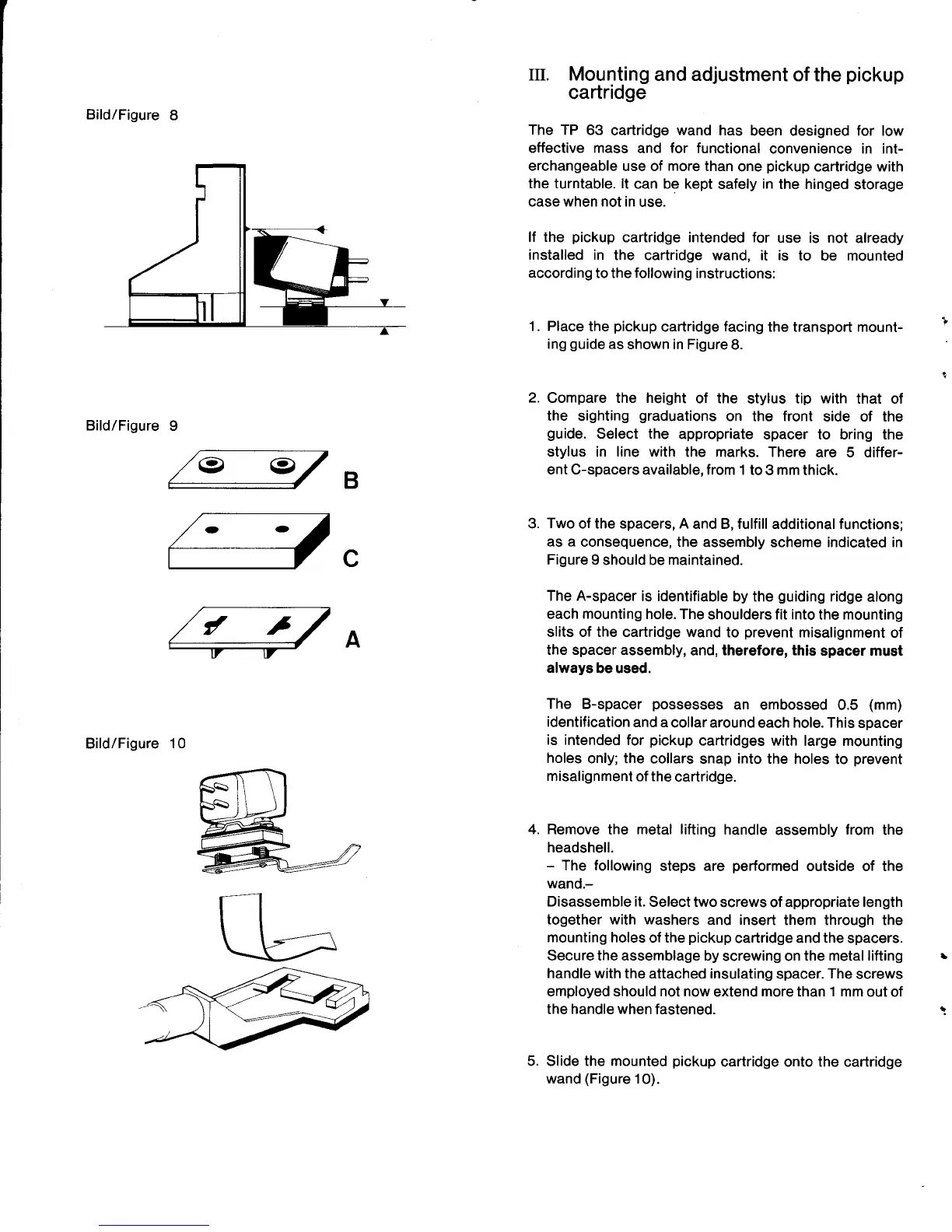
Bild/Figure
8
Bild/Figure
9
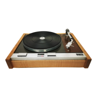
Bild/Figure
10
(D .-
1.
m. Mounting
and adjustment
of the
pickup
cartridge
The
TP 63
cartridge
wand
has
been designed for low
effective mass
and
for
functional
convenience in int-
erchangeable
use of
more
than
one
pickup
cartridge with
the turntable. lt
can be kept
safely
in
the hinged
storage
case when not in
use.
lf the
pickup
cartridge intended for
use is not
already
installed in
the cartridge wand, it is
to be mounted
according
to the following instructions:
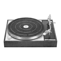
Place
the
pickup
cartridge
facing
the transport mount-
ing
guide
as shown in Figure
8.
Compare the height
of the
stylus tip
with
that of
the sighting
graduations
on the front
side of the
guide.
Select the
appropriate
spacer to bring the
stylus in line with
the marks. There
are 5 differ-
ent
C-spacers available, from 1 to
3
mm
thick.
Two
of the spacers, A
and B, fulfill additional functions;
as a
consequence, the
assembly scheme indicated in
Figure
9
should be
maintained.
The A-spacer
is identifiable
by the
guiding
ridge
along
each
mounting
hole. The
shoulders fit into
the
mounting
slits of the cartridge wand
to
prevent
misalignment
of
the spacer assembly,
and, therefore, this
spacer must
always
be used.
The B-spacer
possesses
an embossed
0.5
(mm)
identification
and a
collar around
each
hole. This
spacer
is
intended for
pickup
cartridges
with large mounting
holes
only; the collars
snap
into
the holes
to
prevent
misalignment
of the
cartridge.
Remove
the metal
lifting
handle
assembly
from
headshell.
-
The following
steps are
performed
outside of
wand.-
Disassemble it.
Select two
screws of appropriate
length
together with washers
and insert
them through the
mounting holes
of the
pickup
cartridge and
the
spacers.
Secure the assemblage by
screwing on
the metal lifting
handle with
the attached insulating
spacer.
The
screws
employed should not now
extend
more
than
1
mm out of
the
handle when
fastened.
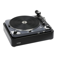
Slide the mounted
pickup
cartridge onto the cartridge
wand
(Figure
10).
B
3.
c
A
the
the
5.
I
I
/
,