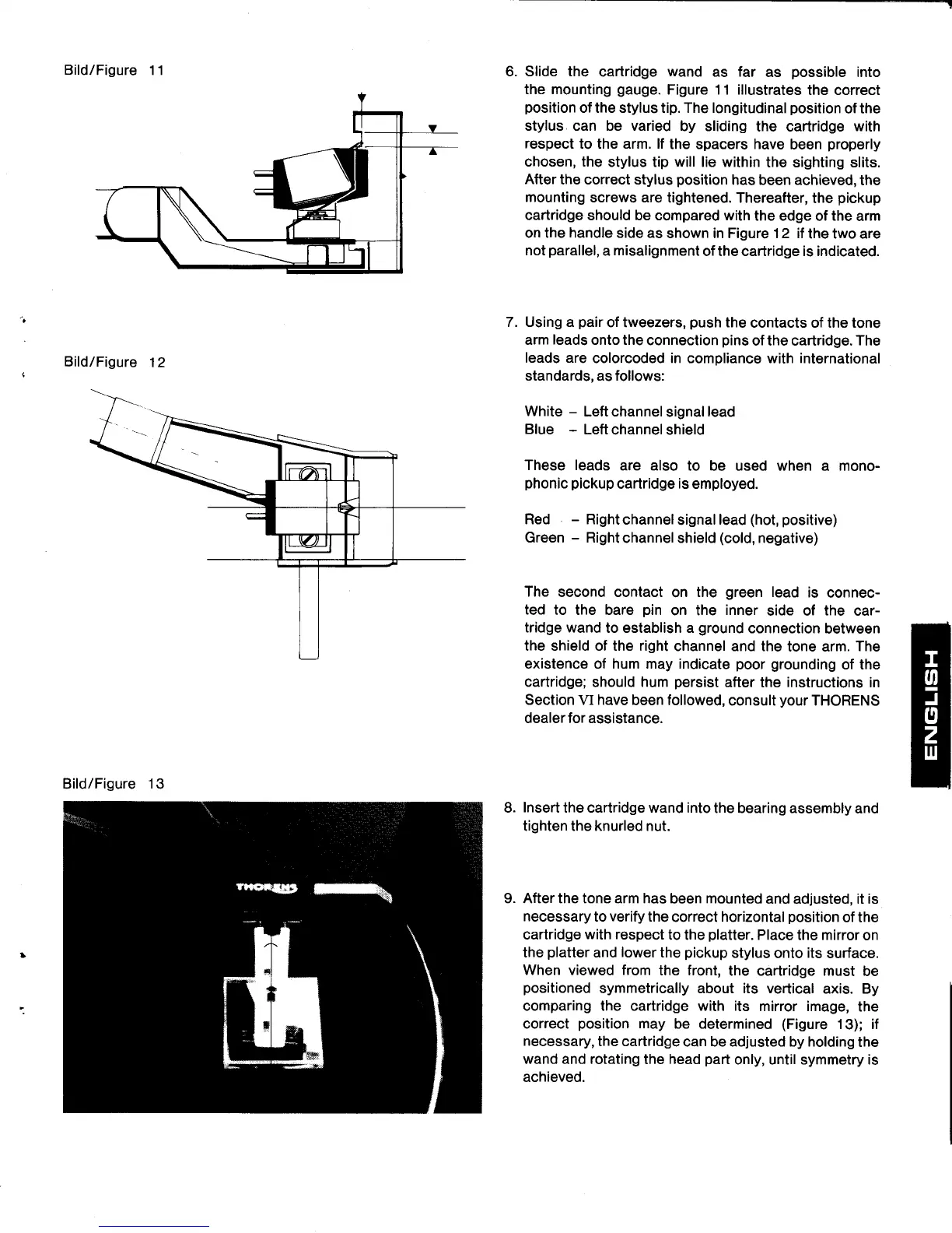
Bild/Figure
11
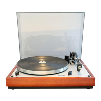
Bild/Figure
12
Slide the
cartridge
wand
as far
as
possible
into
the mounting
gauge.
Figure 11 illustrates
the correct
position
of the stylus
tip.
The longitudinal
position
of the
stylus can be varied
by sliding
the cartridge
with
respect
to the arm. lf
the spacers have
been
properly
chosen, the
stylus tip
will
lie within
the sighting slits.
After
the correct
stylus
position
has been achieved,
the
mounting
screws are
tightened. Thereafter,
the
pickup
cartridge should be compared with
the edge
of
the
arm
on the handle side as
shown in Figure 12 if
the two are
not
parallel,
a
misalignment
of the cartridge is indicated.
7. Using a
pair
of tweezers,
push
the
contacts of the tone
arm
leads
onto the
connection
pins
of the cartridge.
The
leads are
colorcoded in compliance with international
standards, as follows:
White
-
Left channel
signal
lead
Blue
-
Left
channel shield
These leads
are also
to be used when a mono-
phonic pickup
cartridge
is
employed.
Red
-
Right
channel
signal
lead
(hot,
positive)
Green
-
Right
channel shield
(cold,
negative)
The
second contact
on
the
green
lead
is
connec-
ted
to the bare
pin
on the
inner
side of
the
car-
tridge wand
to establish a
ground
connection
between
the shield of the right
channel and the
tone arm.
The
existence of hum may indicate
poor
grounding
of the
cartridge;
should
hum
persist
after
the
instructions
in
Section
VI
have
been followed,
consult
your
THORENS
dealer for assistance.
Insert
the cartridge wand into
the bearing
assembly and
tighten the knurled nut.
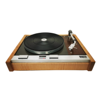
9. After the tone arm has
been mounted
and adjusted, it is
necessary
to
verify
the
correct
horizontal
position
of the
cartridge
with respect
to the
platter.
Place the mirror
on
the
platter
and
lower
the
pickup
stylus
onto
its
surface.
When viewed from
the front,
the cartridge must
be
positioned
symmetrically about its verlical
axis. By
comparing the cartridge with its
mirror image,
the
correct
position
may
be determined
(Figure
13); if
necessary,
the cartridge
can be adjusted by holding
the
wand and rotating
the
head
part
only, until symmetry is
achieved.
8.
Bild/Figure
13