LDC401 & LDC401A Automated Cleavers Chapter 7: Cleaving
Page 18 TTN100064-D02
To change the bottom V-groove insert:
1. Loosen the set screws accessible from the front of the FHB base using the 0.035” hex key included in the
tool kit. Do NOT remove the set screws completely; one full turn counterclockwise should be sufficient to
release the insert.
2. Remove the FHB insert and replace with the desired size. For dual sided inserts, the label for the desired
size should face outward and be visible. For vacuum V-groove inserts (VHD and VHF series), make sure
that the vacuum feed ports are clear of debris by holding the insert up to a light and checking from behind
to make sure light passes each of the ports. Clean if necessary.
3. Make sure that the new insert is fully seated and flush with the inside face of the FHB. Note: The inside
face of the FHB is the side closest to the Cleave Blade.
4. The bottom inserts are secured by re-tightening the set screws until they are snug. Do NOT over tighten.
However see the note below regarding fitment of both inserts in the FHB together. Re-tighten the set screws
until they are snug. Do NOT over tighten.
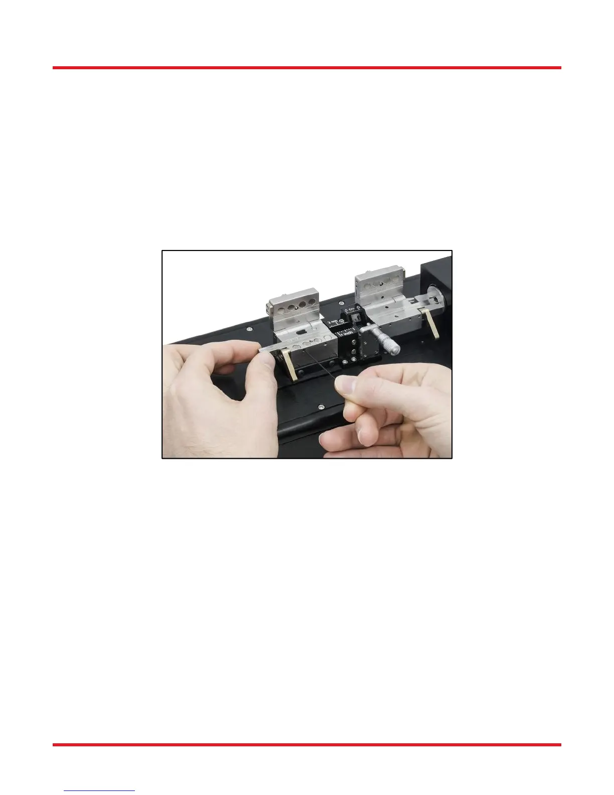
Figure 18 Changing the Bottom Inserts
It is important that both inserts in the FHBs fit together properly. It is better to have both inserts fitted loosely in the
FHBs, and secure them both at the same time:
1. With the lid of the FHB closed only on to the lid lever, but all grub screws that secure both top and bottom
inserts loose, the inserts should be free to move side to side.
2. Use a straight edge to set the ends of the inserts flush to one another on the side of the FHB that faces the
Cleave Blade. It may be useful to use an hex key to push from the other end to get the inserts up against
the straight edge.
3. When the inserts are set side to side, gently raise the lid lever to fully close the FHB Lid.
4. Secure the inserts with the grub screws.
Note: When using the VHF series lower inserts in the left FHB, the Top insert should be fitted differently, not such
that the top and bottom inserts are flush at the inside end. The top insert should be pushed back towards the left,
and 1-2mm clearance between this and the fitted Transfer Clamp allowed, so that the Transfer Clamp Lid may be
easily raised and lowered.
 Loading...